This thread has been locked.

If you have a related question, please click the "Ask a related question" button in the top right corner. The newly created question will be automatically linked to this question.

LMK1C1102: LMK1C1102PWR output enable behavior

Part Number: LMK1C1102


Hello SIr, 

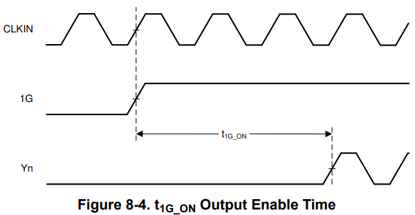
The datasheet of the LMK1C1102PWR mentioned the output needs 5 cycles CLKin, 

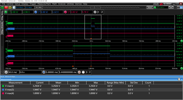
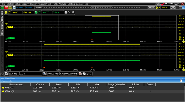
but in our application, the output enabled only used one cycle (as below waveform).

Since currently we're adjusting the FW behavior, we need your opinion to know whether need to adjust it to 5 cycles, 

or just keep it at one time. and what's the exact output enable condition of this part, thank you.

  • William,

    Please note that the output enable time of 5 cycles is the maximum number of cycles it will take to see an effect at the output.  There is no minimum spec listed so your 1 cycle makes sense.  And I'm sorry, what is FW behavior?  Once I know I should be better able to assist with your question.

    Regards,

    Will

  • Hi William,

    Thanks for your reply, currently this FW is just a test program to check the functionality, it's a one-pulse like you see on the waveform to enable this buffer,

    so you mean the 5 cycles in the SPEC are the limited times to retry, and if one CLKin can enable the output, we don't need to add more cycle time for the CLKin, 

    but just in case, adding 5 cycles will more better than one cycle, am I right?

  • William,

    The waveform shows CLKIN and CLKOUT, and not 1G (the output enable)  so it actually is not showing the effect of the the output enable.  If you could capture a waveform including CLKIN, 1G, and the Y (CLKout) then you could see the the clock cycles that it takes to enable the clock outputs as shown in Figure 8-4.  That should give us more information in order to see how many cycles to add.

    Regards,

    Will

  • Hi William,

    The waveform below is our current situation,  the OE/1G pin is always high,

    currently, we have two applications for this part (with two locations),

    The first purpose involves receiving a 1 signal as input. In this scenario, it is acceptable that the output is enabled only after 5 cycles.

    For the second purpose, the pin functions as an interrupt, and only one pulse is present. In this case, we must ascertain whether the interrupt pulse can be blocked by this buffer. Based on the response, it appears that if there is only one pulse at the input, it may not be reflected in the output.

  • William,

    Thank you for the capture, I understand now.  It looks like it is working without the 5 cycle delay, but I will confirm this with our design team and I will test it in the lab tomorrow.  

    Thanks,

    Will

  • William,

    I am sorry for the delay, I will get back to you by the end of the week. 

    Regards,

    Will

  • Hi William,

    Understood, once you find any further information, please let us know in advance,

    our customer is urgent about this issue, thank you.

  • William,

    The first purpose involves receiving a 1 signal as input. In this scenario, it is acceptable that the output is enabled only after 5 cycles.

    This situation will work, as we have discussed, as the clock output will be in 5 cycles or less.

    For the second purpose, the pin functions as an interrupt, and only one pulse is present. In this case, we must ascertain whether the interrupt pulse can be blocked by this buffer.

    In this situation, I tested in the lab and talked to our design team.  The OE is synchronized by the clock by two flip flops (which get reset when VDD is low). So in the situation where the OE is pulled high on startup with VDD and then held high, there will still need to be at least 2 clock cycles to set the flip flops in order to have the output enabled.  So if you only have the OE pulled high on startup, then try to send an interrupt pulse it will not function correctly and no output will be seen.  So on startup you would need to send ~ 5 clock cycles before your interrupt pulse in order to see an output.  

    Regards,
    Will

  • William, 

    How can I support you more on this issue?

    Regards,

    Will

  • Hi William, 

    Thank you for your investigation and analysis. We are currently in the process of confirming with our customer.

    We will inform you once the issue is solved if there are any updates.

  • William,

    Great.

    Regards,

    Will