Hi:
I'm having issues with an LMX2594 not entering LOCK when in VCO_PHASE_SYNC=1 mode.
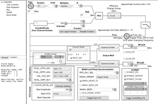
The overall setup is
- fosc=24 MHz
- fPD = 24 MHz
- fVCO = 9600 MHz
- RFoutA = RFoutB = 600 MHz
Because the output is a multiple of fosc (25*24 = 600), this is a Category 2 sync and SYNC is not timing-critical. In my case I have SYNC being applied as a continuous 1.5 MHz clock (so every 16 fosc periods).
The only difference between the two register files (attached) is in R36 (N), which changes between 100 (VCO_PHASE_SYNC=1) and 400 (VCO_PHASE_SYNC=0), as expected because IncludedDivide=4, and R0, which changes from 0x641C (VCO_PHASE_SYNC=1) and 0x241C (VCO_PHASE_SYNC=0) as expected.
The programming procedure follows the LMX2594 datasheet:
- Program RESET=1, then RESET=0
- Program all registers from R112-R0
- Program R0 again
Because SYNC is continuously applied I don't need to toggle VCO_PHASE_SYNC because a SYNC edge comes soon after.
The LMX2594 locks successfully with the LMX_no_sync.txt configuration and outputs the correct frequency, but never locks (and does not output the correct frequency) with LMX_with_sync.txt.
Is there a problem with SYNC being continually applied (even during the VCO calibration sequence)? If so, should I program INPIN_IGNORE=1 in the first programming sequence, and then set INPIN_IGNORE=0 after step 3 above? Or should I switch to the "software" SYNC by toggling VCO_PHASE_SYNC?