Other Parts Discussed in Thread: LMK5B33216
Hello,
We have bought a LMK5B33216EVM board to prototype a component for a radio synchronization system for one customer.
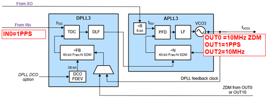
Our goal is to have an LVCMOS input on IN0 (at whatever frequency turns out to be the best one, right now we're using a high-quality signal generator so we are free in our choice), possibly with the same signal generator giving a 48 MHz XO input. We would like to get a 10 MHz signal and a 1-PPS, both in single-ended LVCMOS, the 10 MHz should be 1V8 and the 1-PPS 2V65. The idea would then be to alter the frequency and the phase of the 10 MHz signal (and, correspondingly, of the 1-PPS) in order to achieve synchronization.
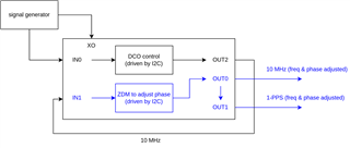
My idea was to use the input on IN0 to generate a 10 MHz signal on OUT2, feed it back to IN1, use ZDM to have an adjustable-phase OUT0 at 10 MHz, and use the same DPLL to generate the 1-PPS on OUT1 (using SYSREF). However, so far any attempt to meaningfully alter the behavior of the board (even in trivial ways) proved fruitless (with the except of the phase adjustment, which I somehow managed to perform).
For instance:
- I load the default configuration
- to minimise the number of changes to the configuration, simply set IN0 and IN1 to CMOS and then feed in IN0_P and IN1_P the requested 25 MHz signal
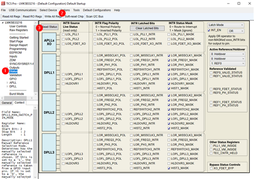
- perform the steps given in the board's user manual
- look at OUT0 and either it blinks or, from time to time, it outputs the correct 25 MHz BUT with an amplitude far lower than 1V8 --- more around 500 mV
The behavior seems to me totally unpredictable, according to the settings I use I sometime get the signal I would expect on OUT1 on OUT0, and vice versa (meaning that, if I request OUT0 to be a 10 MHz signal and OUT1 to be a 25 MHz, I get the opposite). The voltage on OUT1 is usually far lower (sometimes in the order of tens of mV). I measure these signals using a keysight oscilloscope with the input impedence set to 50 ohm. Also, I am using the latest version of TICS Pro.
What am I doing wrong?
Thanks in advance for any help!
Best,
Rob


