This thread has been locked.

If you have a related question, please click the "Ask a related question" button in the top right corner. The newly created question will be automatically linked to this question.

LMK5B33216EVM: TICS Pro settings not applied on LMK5B33216EVM

Part Number: LMK5B33216EVM
Other Parts Discussed in Thread: LMK5B33216

Hello,

We have bought a LMK5B33216EVM board to prototype a component for a radio synchronization system for one customer.

Our goal is to have an LVCMOS input on IN0 (at whatever frequency turns out to be the best one, right now we're using a high-quality signal generator so we are free in our choice), possibly with the same signal generator giving a 48 MHz XO input. We would like to get a 10 MHz signal and a 1-PPS, both in single-ended LVCMOS, the 10 MHz should be 1V8 and the 1-PPS 2V65. The idea would then be to alter the frequency and the phase of the 10 MHz signal (and, correspondingly, of the 1-PPS) in order to achieve synchronization.

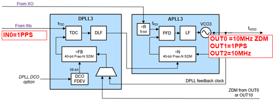
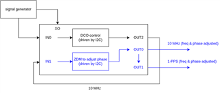
My idea was to use the input on IN0 to generate a 10 MHz signal on OUT2, feed it back to IN1, use ZDM to have an adjustable-phase OUT0 at 10 MHz, and use the same DPLL to generate the 1-PPS on OUT1 (using SYSREF). However, so far any attempt to meaningfully alter the behavior of the board (even in trivial ways) proved fruitless (with the except of the phase adjustment, which I somehow managed to perform).

For instance:

  • I load the default configuration
  • to minimise the number of changes to the configuration, simply set IN0 and IN1 to CMOS and then feed in IN0_P and IN1_P the requested 25 MHz signal
  • perform the steps given in the board's user manual
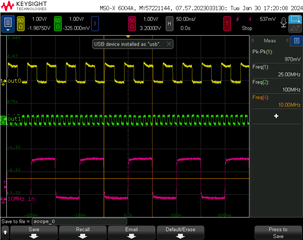
  • look at OUT0 and either it blinks or, from time to time, it outputs the correct 25 MHz BUT with an amplitude far lower than 1V8 --- more around 500 mV

The behavior seems to me totally unpredictable, according to the settings I use I sometime get the signal I would expect on OUT1 on OUT0, and vice versa (meaning that, if I request OUT0 to be a 10 MHz signal and OUT1 to be a 25 MHz, I get the opposite). The voltage on OUT1 is usually far lower (sometimes in the order of tens of mV). I measure these signals using a keysight oscilloscope with the input impedence set to 50 ohm. Also, I am using the latest version of TICS Pro.

What am I doing wrong?

Thanks in advance for any help!

Best,
Rob

  • Hi Rob,

    Can you please provide the .tcs file you are using?

    I'm not following the purpose of IN1 when IN0 is already present. With ZDM enabled, it is not necessary to feedback externally.

    Can you confirm the image below is the configuration you want? It would help if you provided a  block diagram so I can understand your system needs better.

    Regards,

    Jennifer

  • Dear Jennifer,

    Thanks for your reply!
    Actually, I have not prepared a tcs for my use case yet since, as I've mentioned in my post, what I measure on the outputs seems to be totally unrelated with even basic changes wrt the default configuration (e.g., the voltages and frequencies on the outputs are totally wrong) --- so far I've just been playing around, trying to make sense of these values I observe.
    From the datasheet and the literature I thought that the GCD between the input and output frequency should be equal to the input frequency, and from other posts on the forum it looked to me that having a 1-PPS input signal led to extremely long convergence times. This is why I thought about looping back the frequency-adjusted 10 MHz signal for ZDM purposes.

    Please see in the picture here what I had in mind. The overall idea is that an external PC extracts timing information from a radio signal and performs adjustments on-the-fly via I2C on the generated signals (e.g., increase the generated 10 MHz frequency by 0.001 Hz and phase-shift it by 2 ns), and those adjustments happen at a sustained rate (ideally once every 1 or 2 seconds) --- which would be incompatible with the 30-50 minutes convergence time that are mentioned in the posts discussing about 1-PPS inputs. The 1-PPS generated by the LMK5B33216 should be aligned with the 10 MHz (meaning it should have its rising edges every 1e7-th rising edge of the 10 MHz signal), with a duty cycle of minimum 25%.

    Can this be achieved with the LMK5B33216?
    Thanks again and have a nice day!

    Regards,
    Rob

  • Hi Rob,

    1. I'm unable to click on the image link due to my company's firewall. Can you please upload a screenshot here?
    2. "The overall idea is that an external PC extracts timing information from a radio signal and performs adjustments on-the-fly via I2C on the generated signals (e.g., increase the generated 10 MHz frequency by 0.001 Hz and phase-shift it by 2 ns), and those adjustments happen at a sustained rate (ideally once every 1 or 2 seconds"
      1. This is possible by using the DPLL DCO (digitally controlled oscillator) which allows you to make frequency and phase adjustments of <1ppb accuracy.
    3. "which would be incompatible with the 30-50 minutes convergence time that are mentioned in the posts discussing about 1-PPS inputs."
      1. We have recently improved our register settings to allow for faster lock time.
      2. If the initial XO error is ±25ppb, it could take as low as 38s for the DPLL to lock. With 1-PPS +ZDM configured, it could take 8min for the DPLL to lock.
    4. "The 1-PPS generated by the LMK5B33216 should be aligned with the 10 MHz (meaning it should have its rising edges every 1e7-th rising edge of the 10 MHz signal), with a duty cycle of minimum 25%."
      1. The LMK5B33216 can only output 50% duty cycle.
    5. My apologies, I re-read your original testing procedure again. Let's focus on getting the default resolved first before working on another config with ZDM, that way we are on the same page with the setup.
    6. With that, please repeat your previous EVM setup. In TICSPRO, please navigate to the Status page, issue a SWRST, click "Read Status", then send a screenshot of what you see.

    Regards,

    Jennifer

  • Hello Jennifer,

    1. Here's a diagram of the structure I had in mind:


    2. Yes, the (extremely) high adjustability of the IC using the DCO is what drove us to buy it :)
    3. From our previous PoC (where no external clock generator was used), the error between the reference and the desired target is initially in the 1-3 ppm range. The initial iterations of our algorithm are (relatively) high-frequency (~ 1Hz), then the system rapidly converges. Our PoC had poor adjustability and thus we had to keep a ~1 Hz frequency all along, but our goal with the LMK5B33216 is to progressively lower the interval between re-synchronizations to once every some tens of seconds --- which, if I understood your reply correctly, it is still faster than what could be achieved with 1-PPS+ZDM.
    4. A 50% duty cycle would be fine by us (we have a lower bound, but no upper one).
    5+6. With pleasure, thanks! This is what I've done:
      - started TICS Pro, restored the Default Configuration
      - in the Start Page, set the following values:
        - IN0 Freq 10 MHz, Interface type: CMOS
        - IN1 Freq 0 (unused)
        - OUT1 Output Format: CMOS 2.65-V. P/N = On
        - disabled all outputs other than OUT0 and OUT1
        - clicked calculate + copy + assign + apply
      - started the signal generator, with a 10 MHz square wave (2 Vpp, +1 V offset) sent into IN0_P
      - connected the oscilloscope, 50 ohm on inputs, yellow trace is the probe connected to OUT0_P, the green trace is the probe connected to OUT1_P, and the pink one is the signal from the signal generator (that also goes into IN0_P)
      - connected the board, clicked again on apply -> the frequencies of the board's outputs change -- e.g., OUT0 was 5 MHz before -- so we should have correctly applied our configuration.

    Please find below (1) a screenshot of the current status in TICS Pro (after several minutes of execution), and (2) a capture on the oscilloscope.
    The amplitudes are wrong (in particular for OUT1 --- no amount of weirdness on the cables should be able to make a 2V65 signal become 1/5th of itself)


    I am of course doing something horribly wrong (sorry, not my area of expertise... :-( ), could you please help me in figuring out what exactly is my issue / point me to the appropriate documentation (I've read twice the whole LMK datasheet, and now I can understand most of the options in TICS Pro, but it is evident that I am still missing something crucial...).

    Thanks again!
    Regards,
    Rob

  • Hi Rob,

    Thanks for sending the detailed flow. I will review and work to get back to you later this week.

    In the meantime, we also have the EVM User's Guide, not sure if you've seen it already. There's a section in the Appendix that contains TICSPRO guide .

    Regards,

    Jennifer

  • Hello Jennifer,

    Yes, sorry, I've forgot to mention it. I've already gone over the user manual.
    Should this help you in figuring out my issue, please find below the actual configuration I've used for the tests above.

    Thanks again!
    Regards,
    Rob

    first_attempt.tcs

  • Dear Jennifer,

    Very sorry to put some pressure, but I am still stuck :(
    Have you managed to find the issue in what I have been doing?

    Thanks a lot for your help and understanding!

    Best,
    Rob

  • Hi Rob,

    My apologies for the delay.

    Can you please try again with this file?

    e2e_lmk5b33216_first_attempt, feb122024.tcs

    Also, please note that the default EVM setting for OUT1 has HCSL termination (50-ohms to GND on each P and N leg). If you would like to test with CMOS outputs, I recommend removing such resistors.

    Regards,

    Jennifer

  • Hello Jennifer,

    Thanks! Things start to work here :) With your config I have OUT0 which is now 1.7 Vpp.
    I still had OUT1 which was active on both _P and _N, each with ~ 1.4 Vpp, oscillating around 0 V. By looking at the schematics I've seen both the 50 ohm resistor you've mentioned, and the capacitor closer to the IC. I'll remove R168 and replace the capacitor with a 0 ohm.
    Also, by exploring a bit the raw register values, I've seen that some (e.g., R965 and R967) were not set to the correct values. Apparently the GUI does not set them correctly, since writing the values by hand does the job.

    Thanks again for your help in solving this issue! I'll now start the configuration for the application we have, and get back to you should I get stuck at some point.

    Regards,

    Rob

  • Hi Rob,

    That's good to hear. Please make sure to run through the Start Page step by step and hit "Run Script" at the end to ensure the DPLL can lock to the entered input frequency.

    Regards,

    Jennifer