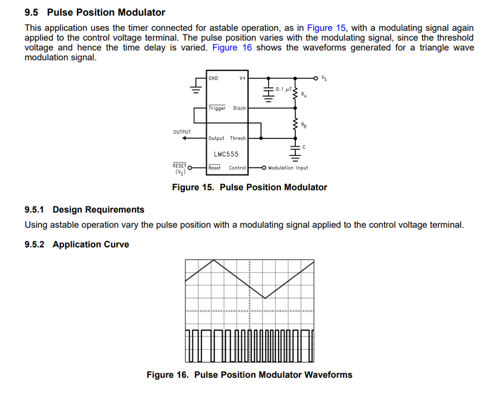
Hello, I'm utilizing the LMC555 timer to produce PWM with a duty cycle between 45-55% and a frequency of 84.5KHz. The timer is set up in A-stable mode, and I'm facing challenges in understanding two key aspects. Firstly, I have two MCUs arranged in parallel, and for redundancy purposes, I'm using them to generate signals sent to the AND gate. The AND gate's output is intended to drive the timer for PWM signal generation. I'm uncertain about the pin operation, specifically whether the output of the AND gate should be connected to the TRIG pin or the control voltage pin. Your insights would be appreciated. Thanks!


