This thread has been locked.

If you have a related question, please click the "Ask a related question" button in the top right corner. The newly created question will be automatically linked to this question.

LMX2571: Losing lock at high temperatures

Part Number: LMX2571


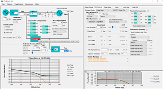
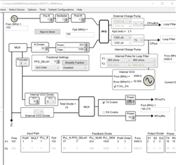
We use the LMX2571 in a design to generate 190 MHz LO for a receiver downconverter.

It loses lock when the board temperature reaches roughly 65 °C. It seems to only loose lock in a narrow temperature range and I’m finding it difficult to repeat the issue reliably (on demand). 

I have confirmed that the input clock (a 100 MHz TCXO) and power supply is stable.

Could you please help with suggestions on what to test/measure/verify to narrow down the cause?

  • Hello Pieter, 
    Our devices usually only unlock for two reasons, an external disturbance or the reference being lost. 
    Can you monitor that reference at OSCIN at this temperature range? 

    Regards, 

    Vicente 

  • Hello Vicente,

    Yes, I can monitor OSCIN, but slightly indirectly. The output of TCXO goes to LMX2571 and FPGA. FPGA counts the pulses and latches it with 1 pps from GNSS to measure clock accuracy. We are 12 Hz off on 100 MHz, so my assumption is that the ref clock is stable. This would not pick up duty-cycle or short-term cycle issues but these are highly unlikely given my measurement.

    I say "indirectly" because the TCXO output is split in these two paths, and each path has its own 10 ohm resistor at the source to provide isolation between digital and RF domains.

    My N divider is 45.655. When using PLLatinum Sim it gave a message saying that N must be greater than 48, but I did not find this in any documentation. I am meeting VCO ranges. Am I missing something, and can this explain my issue?

    Do you think it is worth bringing out OSCIN from input of LX2571 (difficult, but possible)? Anything else?

    The lock does not auto-recover, but if I re-initialise all registers, it does recover. Would the loss of lock be latched?

  • Hi Pieter, 
    Can you provide a copy of your configuration? Preferably a .tcs file? 
    Assuming a100 MHz input; 100 MHz PDF and 190 MHz RFout implies PLL N divider should be 22 + 4/5

    It seems like your reference is stable in that case. 

    Do you see this issue for various units or is this isolated to one unit?

    Regards, 

    Vicente 

  • Hi Vicente,

    I see this issue on all the units where we tested it. We've build hundreds where the temperature spec was 55 but a customer requested 65 and we found it on the first 10x.

    Attached is my .tcs file with the registers it generated. I confirmed that I read back the same values after initialisation and they are also still valid when I see the issue. There is one exception though. In R0, I have 0x283. I set F1F2_MODE during initialisation but also if the frequency should change.

    Regards,

    Pieter

    LMX2571_190MHz.tcs

    R60	0x3CA000
    
    R58	0x3A8C00


    R53	0x357806


    R47	0x2F0000
    R46	0x2E001A


    R42	0x2A0230
    R41	0x290810
    R40	0x28101C
    R39	0x2711FB


    R35	0x230C83
    R34	0x221000
    R33	0x210000
    R32	0x200000
    R31	0x1F0000
    R30	0x1E0000
    R29	0x1D0000
    R28	0x1C0000
    R27	0x1B0000
    R26	0x1A0000
    R25	0x190000
    R24	0x180010
    R23	0x171044
    R22	0x1684A1
    R21	0x150101
    R20	0x143019
    R19	0x1307D0
    R18	0x120378
    R17	0x110000
    R16	0x100000
    R15	0x0F0000
    R14	0x0E0000
    R13	0x0D0000
    R12	0x0C0000
    R11	0x0B0000
    R10	0x0A0000
    R9	0x090000
    R8	0x080010
    R7	0x071084
    R6	0x068AA1
    R5	0x050101
    R4	0x043016
    R3	0x0303E8
    R2	0x020341
    R1	0x010000
    R0	0x000083
    

  • Hi Pieter, 
    I see RFout is 190.275 MHz, I just  want to be sure this is the desired frequency? 

    Can you please monitor the VTUNE voltage across temperature?
    Can you send me your loop filter? 

    Are you programming R0 to ensure VCO calibration? 

    Regards, 

    Vicente 

  • Hi Vicente,

    I see RFout is 190.275 MHz, I just  want to be sure this is the desired frequency? 

    Yes. I rounded down for simplicity when I originally mentioned 190 MHz.

    Can you please monitor the VTUNE voltage across temperature?

    Should be possible. It means a wire to the chamber which will add capacitance but hopefully this does not change the problem.

    To be clear: Are you talking about CPout pin, 25?

    Can you send me your loop filter?

    3rd order: 270 pF in parallel with (5n6 in series with 560R).

    Are you programming R0 to ensure VCO calibration?

    Yes. R0 is written with F1F2_MODE and FCAL_EN set.

    Regards,

    Pieter

  • Hi Pieter, 

    Yes. I rounded down for simplicity when I originally mentioned 190 MHz.

    - Just wanted to be sure. 

    To be clear: Are you talking about CPout pin, 25?

    - That is correct. 

    Please monitor VTUNE over temperature. 


    What is your target loop bandwidth? 
    Using your configuration you provided and the the values for C1/C2/R2 you provided I get an loop BW of ~132kHz filter using PLLatinumSim? Overall your loop filter seems stable thus I don't think the loop filter is the cause for unlock.

    Please try reducing the fractional engine from 3rd order to 2nd order & see if this solves the unlock issue. It's possible you're at the border of the minimum N divider value using 3rd order and at high temperature this causes unlock. 

    Regards, 

    Vicente 

  • Hi Vicente,

    I've added a second unit to my setup and changed the order of the sigma-delta modulator on both to 2nd order. It made no difference. I also changed it to 1 without any effect.

    I can indirectly see the output of the synth by looking at our downconverter data. I saw that the new unit starts to show spurs at lower temperatures (from about 50 degC). I am going to open that unit, and see if I can get a wire in to measure VTUNE. I need to modify some metalwork to do this, so it may take a day or two to get a result. If there is anything else you can think that I can try to narrow the search area, please let me know.

    Regards,

    Pieter

  • I now have some more data (VCO measurements) to add in addition to my previous reply.

    I have attached my measurements as a .pdf file with explanations of how it was measured in the .pdf file. All measurements were done with new 2nd order fractional engine (even though it made no difference).

    I also tried something else: I changed the output frequency to 200 MHz so that N could be 48 (NUM=0; DEN=1000). This to see if it would make a difference. I got exactly the same results as those shown in the attached .pdf file.

    I also learned a little bit more today:

    1. The issue seems to only happen in a narrow temperature band from ~65 degC to ~70 degC. I have not been able to reproduce the issue below or above these temperatures.
    2. The issue seems to only manifest at startup (powering up, or doing software reset of my board). It does not seem to happen if I switch it on at low temperature, and then let the board heat up. I am almost always able to recover by re-initialilsing, but as you will see in the .pdf file there are certain times when the VCO oscillates violently where re-initialisation has no effect.

    Is there anything else that I can measure that may help me resolve this issue?

    LMX2571 VCO Measurements.pdf

  • Hi Pieter, 

    After having gone through your PDF I have one question, you say you perform a reset? Can you elaborate? Do you software reset, power cycle? You talk about resetting only the board so I want to be sure I understand what you mean by reset and what is being reset exactly. 

    Are you reprogramming all device registers after this reset? I ask due to last slide as well where you state you reprogram the device and recalibrate the VCO. 

    If you're resetting the device, you will need to reprogram it & recalibrate the VCO. A reset to LMX2571 will cause the device to revert back to silicon default which requires you to reprogram. I believe when you say "reinitialize" you mean reprogram? 

    Can you please provide DS of their TCXO? What is the output Swing/format? How do you connect the TCXO to the receivers? 

    Regards, 

    Vicente

  • Hi Vicente,

    Thanks again for getting back to me, it is much appreciated.

    I apologise, my explanation was not clear. I have two kinds of system reset:

    1. Power On Reset
    2. Software Reset

    I used "reset" for both as they should be very similar from the Synthesizer point of view. CE (pin 19) is pulled low with 10k resistor. It is connected to CPU GPIO that is tri-stated by default. It is only changed to GPIO about 5 seconds after reset and then pulled high by CPU. In both cases the CE line will be low, and will be pulled high after about 5 seconds.

    The software waits for 100 us and then initialises the LMX2571: It writes R0 with the RESET bit, default values as required by datasheet and FCAL_EN set. After writing R0 with RESET there is no delay before it continues to write all the registers from R60, through to R0. The last write to R0 sets the recalibrate bit (FCAL_EN).

    "reinitialise" calls the initialise function that writes R0 then R60 through R0 as mentioned above.

    Attached below is the datasheet for the VCXO. The output of the VCXO is connected to OSCin (pin 34) with 10R in series. There is another 10R in parallel that connects the VCXO output to an FPGA. \OSCin (pin 36) is left floating.

    Thank you again for your comments. It made me think about stability of the VCXO at start-up, so I will try to add it to my measurement tomorrow.

    CVHD-037X.pdf

  • Hi Pieter, 
    Okay, CE is controlled by GPIO pin on MCU and is high by default. 

    So you power up the device and perform a software reset by toggling R0[13] -> 1 


    From here you program starting from R60 down to R0 again. 
    Every time you perform any reset, are you programming R60 to R0 once again? This is required. 

    Okay looks like its a VCXO. The swing seems okay. 
    Can you provide a copy of schematic? I wish to see how exactly it's connected. 

    Regards, 

    Vicente 

  • Hi Vicente,

    Okay, CE is controlled by GPIO pin on MCU and is high by default.

    No, it is pulled low with 10k resistor, so I see this as the default value when power is applied. The CPU pulls it high as part of the GPIO initialisation. It means it is pulled high about 5 seconds after power is applied, and the code starts to write registers 100 us after it is pulled high.

    From here you program starting from R60 down to R0 again. 

    Correct.

    Every time you perform any reset, are you programming R60 to R0 once again? This is required.

    Correct. The Synth_Init() function that is called after power up, or on command will always write R0 (by setting R0[13] to 1) then R60 through R0.

    Can you provide a copy of schematic? I wish to see how exactly it's connected.

    Do you have e-mail (or other means) for me to share this privately? I cannot share company schematics on an open forum.

    I am currently busy with my tests where I am monitoring VCO and Clock. My horizontal resolution on the scope is 50 us/div, so I am effectively only looking at the envelope of the clock and this is not showing any issues. I have however not been able to reproduce the issue since I am monitoring the clock. It is still too early to say conclusively, but maybe the probe loading on the clock is having just enough effect to hide the issue. I will have more info at the end of the day after more exhaustive testing.

    Regards,

    Pieter

  • Hi Pieter, 
    Yes you can email me at v-floresprado@ti.com . 
    Please send a pdf if possible, makes reading much more easier. 

    Regards, 

    Vicente 

  • Hello Vicente,

    Thanks again for the help in solving a complex issue. To close the loop, I've marked your first response as the correct one as the issue was on the OSCIN pin.

    For anyone else reading, it was not straight forward though: My CMOS oscillator output is split in two and the one path contained a reflection of a high-order harmonic (that I could not see on oscilloscope) that seemed to confuse the LMX2571 calibration process (it was not a VCO issue). A very small 15 pF capacitor was added to filter high-frequency components and this resolved my issue.