This thread has been locked.

If you have a related question, please click the "Ask a related question" button in the top right corner. The newly created question will be automatically linked to this question.

CDCE62005 Driver

Other Parts Discussed in Thread: CDCE62005

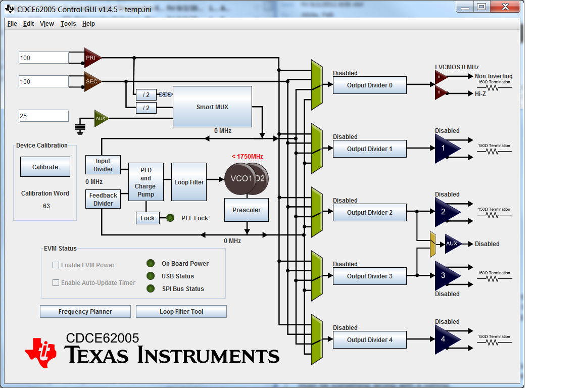
I am using the CDCE62005 exclusively for its smart mux selection feature (and using it as a divide by 2). I have 2  LVCMOS inputs, each are 100 MHz CMOS inputs. I have output 0 positive set to 50 MHz CMOS. My current Register values are as follows:

REG0000 2100011

REG0001 6800011

REG0002 6800010

REG0003 6800010

REG0004 6800011

REG0005 00007EC

REG0006 003F19A

REG0007 BD0037F

Does that make sense? Specifically I am wondering about the input termination settings, but a general check would be nice since it doesn't seem to be working. Are there any caveats or gotchas I should be aware of while programming it? I appreciate all your time and help!!!!


I have used chipscope pro to verify that my writes are working and my reads.  I read the default configuration properly, wrote a register and then read back what I wrote.  There must be something wrong with a setting...

  • Chris,

     your input settings seem alright. CMOS doesn't use input termination, so if you have a long transmission line, you will either need to source termination or external to the device. I did however find another problem: your output divider on output 0 is set to div-4. I think you are trying to output 50MHz, right? If so, set register 0 to:

    REG0000 2040011

    By the way, you should load your settings into the GUI, this way you can graphically see your settings. here a screen shot with the changes in Reg 0:


    here the file you can load into your GUI:

    http://e2e.ti.com/cfs-file.ashx/__key/CommunityServer-Discussions-Components-Files/48/2021.100MHz_5F00_smartmux_5F00_bypass_5F00_mode.ini

    Best regards, Fritz

  • Fritz,

    Are you sure it shouldn't be 2100011?  Bit 20 should be a 1 to enable the divider and bit 18 should be 0 right?  Also I have downloaded the GUI but when I try to install I get an error...  I appreciate you taking the time to look over my settings!

    Thanks,

    Chris

  • Chris,

    you can download the latest GUI here, we just released it:

    http://e2e.ti.com/support/clocks/m/videos__files/353682.aspx


    if you have a GUI error with XP, make sure you have the latest JAVA update. If you have a WIn-7 machine, it should work fine.

    In a divide-by-1 case, you are correct, I just checked, the divider needs to stay on. check table 24 in ther CDCE62005 data sheet for the right setting for div-1. it's in the 2nd rown.


    By the way, I learned another thing that i think will be really helpful. Instead of dividing by 2 in the pre-divider, do it in the output divider. The reason is that the smartmux can cause duty-cycle errors. Dividing down the output by 2 will get rid of the duty cycle error. BR Fritz

  • Fritz,


    I appreciate that and will make the change you suggested! 

    With that change not yet made the updates have provided an output, but it looks like the output I would expect if the CMOS was somehow be AC-coupled.  Is there any way you can  think of that might happen?


    Thanks,

    Chris

  • Register values are now as follows:

    REG0000 2180012

    REG0001 6800012

    REG0002 6800010

    REG0003 6800010

    REG0004 6800011

    REG0005 00007EC

    REG0006 003F002

    REG0007 BD0037F

    REG0008 40005DD


    Thanks,

    Chris

  • Chris,

    If you are using the TI EVM, it deploys AC coupling caps on every output. Check out the EVM manual, to overcome the onboard termination and AC coupling. Hope this helps! If not, shoot me a measured waveform. Best regards! Fritz

  • Fritz,


    Unfortunately I am not using the EVM, I have a 10 ohm series resistor output termination.


    Thanks,

    Chris

  • Chris,

    that sounds iffy. the 10-Ohm should be fine. The output stage has a pure CMOS output driver when CMOS is selected, so no AC coupling. Can you describe what you are seeing or even better show a screen shot? Make sure scope is not AC coupled internally. BR Fritz