Part Number: LMX2491
Other Parts Discussed in Thread: LMX2492, LMX2595
Dear TI Support Team,
"End-result" problem description:
We wrote a micro controller program to write the registers to the LMX2491. We did this in a loop starting from register 0 going upwards. The exact values we are writing this way were exported and parsed to C-Code (for handling by our microcontroller with TICS Pro.
We observed (externally) that ramp profiles written to the PLL produce different ouputs (i.e. different start/end frequencies) when writing the same register map multiple times. Sometimes the ramps were shifted down by several (tenths of) MHz, sometimes up and only after the third writing cycle (of the exact same register map), the image "stabilized".
We also used the read-back functionality (after each individual register write!) to confirm that the register was written correclty to the PLL.
What we did to debug:
instead of writing registers one-by-one we tried to use the "continuous writing" as described in the datasheet and found that doing it this way, the PLL "does what it should do" and sequential repetition of writing the same register map does not result in the observed "odd" behaviour.
We then tried to use our initial "write one-by-one and check after each register" schema but starting from R141 (i.e. the highest one) and indeed: Performing the write in "REVERSE order" does actually solve our problem as descripbed above.
Request to you:
The LMX2491 and LMX2492 datasheets state:
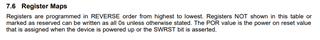
Registers are programmed in REVERSE order from highest to lowest.
We first understood that this sentence is applicable only to the single block writing "option" as described in "Loading registers".
The user has the option to pull the LE terminal
high after this data, or keep sending data and it applies this data to the next lower register. So instead of sending
three registers of 24 bits each, one could send a single 40-bit register with the 16 bits of address and 24 bits of
data. For that matter, the entire device could be programmed as a single register if desired.
Please consider following suggestions:
a) Change the sentence to "Registers MUST be programmed in REVERSE order from highest to lowest".
b) Improve the datasheet generally by adding a "recommended power-up sequence" more or less identical to the LMX2595 datasheet:
7.5.1 Recommended Initial Power-Up Sequence
For the most reliable programming, TI recommends this procedure::
1. Apply power to device.
2. Program RESET = 1 to reset registers.
3. Program RESET = 0 to remove reset.
4. Program registers as shown in the register map in REVERSE order from highest to lowest.
5. Wait 10 ms.
6. Program register R0 one additional time with FCAL_EN = 1 to ensure that the VCO calibration runs from a
stable state. (This last step is probably not applicable to the LMX2491 / LMX2492-series?
Could you please also explain
c) why this writing in reverse order does have such a big importance and why things behave so "strange" when not following this rule?
d) Are there blocks or individual registers which can be written individually or is it ALWAYS required to write all 142 registers ?