This thread has been locked.

If you have a related question, please click the "Ask a related question" button in the top right corner. The newly created question will be automatically linked to this question.

CDCE62002: CDCE62002 - Wrong output frequency

Part Number: CDCE62002


Hi,

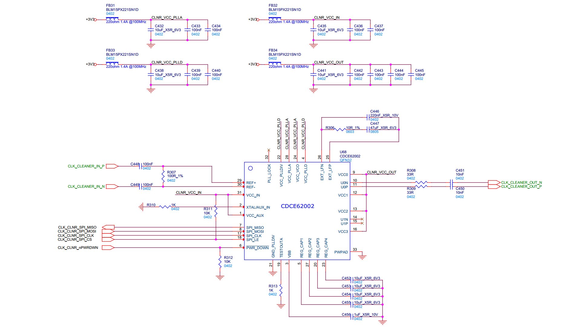
I am currently experiencing an issue with the clock cleaner CDCE62002.
I use the clock cleaner to convert frequencies from 74.25 MHz to 74.25MHz or 148.5 MHz to 148.5 MHz. I need a perfect x1 conversion.
Most of the time, the output frequency is correct; however, sometimes it's not.
The problem arises exclusively when transitioning the input signal from one frequency to another (e.g., from 148.5M to 74.25M, or vice versa).
When the output frequency is incorrect, it's typically quite close, around 74.35 MHz / 148.55 MHz. This is not precise enough for my needs.

Below are the register values I use for converting 148.5 MHz to 148.5 MHz:
Reg0: 0x10360050
Reg1: 0x9782E061

After setting these values in the registers, I initiate a calibration by toggling PD:
Reg2: 0x01001802
Reg2: 0x01001002
Reg2: 0x01001802

Then, I wait until PLLLOCKPIN equals '1'.

The external filter has the following values: 220nF, 10R and 47uF.
The input has an AC termination.

  • Hello,

    So to clarify. You have two configurations: 74.25 MHz to 74.25MHz and 148.5 MHz to 148.5 MHz. And the problem arises when you are switching from the 74.25 MHz config to the 148.5 MHz config and vice versa, correct? Can you provide your 74.25 MHz config as well? And does this config have the same external filter values? We can try to reproduce this issue on the bench.

    Best,

    Cris

  • Hi Cris,

    Below is my 74.25 MHz configuration:

    Reg0: 0x10660050
    Reg1: 0x9782E021

    The external filter always has the same values whatever the frequency is.

  • Hello,

    We will try to replicate this issue on the bench. Expect an update later this week.

    Best,

    Cris

  • Hello,

    So far, I have not been able to replicate the issue. I have some additional questions.

    Most of the time, the output frequency is correct; however, sometimes it's not.

    - How often does the issue occur? One out of 10? One out of 50? 

    - Is this only occurring on one device? 

    The problem arises exclusively when transitioning the input signal from one frequency to another

    - What is the order of the input frequency change, rewrite the device, toggle PD for recalibration sequence? What is the timing between each step?

    Best,

    Cris

  • Hi Cris,

    Turns out I had it wrong about the problem just popping up with frequency changes.
    After some digging, I realized it's actually triggered by high ambient temperatures (above +65 °C).
    You can replicate it by simply reconfiguring the PLL multiple times; no need to tweak the frequency.
    The issue occurs on every device.

    I managed to nail down the correct register configuration using the internal filter (I was using the external one before):
    R0: 0x10360050
    R1: 0x8382E061
    Now it works pretty well.

    Got any idea why the external filter doesn't work well with high temperatures?

    Here's how I'm setting things up:
    1) Write R0 register
    2) Write R1 register
    3) Set PD = 0 (R2 = 0x01001802)
    4) Wait 50 ms
    5) Set PD = 1 (R2 = 0x01001002)
    6) Wait 50 ms
    7) Set PD = 0 (R2 = 0x01001802)
    8) Wait 50 ms
    9) Wait until the PLL is locked (bit 6 of register 2)

  • Hello,

    Are you using one of our EVMs or your own PCB? If you are using your own PCB, can you share your schematic and layout?

    Best,

    Cris

  • Hi,

    I use my own board.

    Here's the schematic:

  • Hello,

    Thank you. We will look into this and get back to you tomorrow.

    Best,

    Cris

  • Hello,

    I was unable to recreate the issue at 70C with our EVM. It's possible the capacitors used in your layout are causing the issue. As they are external components, we are not able to exhaust all possible combinations during testing. Here's what we use on our EVMs:

    - C111 [C446 on your schematic] 0.22µF 0603 X7R +-10% 25V Venkel C0603X7R250-224KNE

    - C118 [C447 on your schematic] 47µF 1206 X5R +-20% 6.3V Venkel C1206X5R6R3-476MNE

    Alternatively, you could continue to use the internal loop filter as this was tested up to the rated +85C.

    Best,

    Cris