This thread has been locked.

If you have a related question, please click the "Ask a related question" button in the top right corner. The newly created question will be automatically linked to this question.

LMK04832: TICS Pro Register inconsistency

Part Number: LMK04832

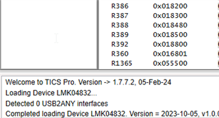
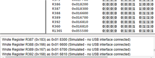
The TICS Pro (V1.7.7.2) Register Map has inconsistency. see below - the last few entries

R387    0x018300
R388    0x016600 -- the left and right side address mismatch
R389    0x016700 -- the left and right side address mismatch
R392    0x016810 -- the left and right side address mismatch
R360    0x016810
R1365    0x055500

  • My freshly installed v1.7.7.2 LMK04832 shows:

    In C:\ProgramData\Texas Instruments\TICS Pro\Configurations\Devices\Clock Generator-Jitter Cleaner (Dual Loop)\LMK04832\LMK04832.ini, the main database for the profile, I see in the [REGISTERS] section:

    NAME119=R386
    MASK119=0
    VALUE119=98816
    NAME120=R387
    MASK120=0
    VALUE120=99072
    NAME121=R388
    MASK121=0
    VALUE121=99456
    NAME122=R389
    MASK122=0
    VALUE122=99584
    NAME123=R392
    MASK123=0
    VALUE123=100352
    NAME124=R360
    MASK124=0
    VALUE124=92172
    NAME125=R1365
    MASK125=0
    VALUE125=349440

    The value of VALUE120, VALUE121, and VALUE122 comes out to 0x18300, 0x18480, and 0x18500, respectively.

    I attempted loading a tcs file, and found that TICS Pro accepts register name and address value mismatches in the [MODES] section:

    NAME120=R387
    VALUE120=99072
    NAME121=R388
    VALUE121=91648
    NAME122=R389
    VALUE122=91904
    NAME123=R392
    VALUE123=92176
    NAME124=R360
    VALUE124=92176
    NAME125=R1365
    VALUE125=349440

    To avoid this data corruption, the name keys need to match the order and value of the name keys in LMK04832.ini, and the values written with each name key need to belong to that specific name key. Correct your TCS file [MODES] section to match LMK04832.ini [REGISTERS] section order.

    The root cause of this issue was a rearranging of the register order in LMK04832 profile a few months ago, combined with the heretofore unknown order requirements for the [MODES] section keys. Older TCS files saved their [MODES] section keys using the old ordering, and will now load in incorrectly.

    Due to bad decisions made a decade ago (mainly the choice to allow repeated registers to appear in the register map, see R0 and R0 (INIT) in LMK04832), we can't trivially solve this issue by parsing out the address of the value portion of the [MODES] section and using that as the register address. But if you're seeing this issue now, it means others can also see this issue and may not realize the wrong register data is being written for these three registers. Fortunately for all of us, in this instance, the three affected registers (R388, R389, and R392) are readback diagnostic registers and are not critical to the configuration. But this issue is also a potential problem in other profiles as well. I will reflect on a potential solution and include something for TICS Pro 1.7.7.3.

  • Thanks Derek. it was too challenging to merge the sections. so i

    1. deleted the existing "bad" tcs designs

    2. uninstalled the TICS Pro 1.7.7.3 program

    3. deleted any remnant folders in programs/program data

    4. reinstalled   TICS Pro 1.7.7.3

    and will work from here. is this alright?

    thanks again.

    historically, there is always some difficulty in getting the synthesizer/clean up chips to work (from all manufacturers). the data sheets does not quite tell you all. the clock programming tool also does not give you everything you need.

    as a user, the expectation from TICS Pro is

    1. a list of registers to program in correct order (repeats are quite fine!)

    2. additional info to wait between two register writes

        a) perhaps some bias needs to power up inside the chip - so wait some milli-seconds

        b) perhaps something needs to lock/calibrate inside the chip - so either wait a while or read back a register

    3. is there anything else to know?

    how to get this second part?

    regards,

    joseph

  • For part 1, we do have a long-term solution planned where we separate out the programming sequence from the register map data; that way you can generate programming sequences independently from configuration data. There's also ways to represent the configuration data as an abstraction of "things I want to do" e.g. I need this frequency plan and I need to synchronize the phase such that input is aligned to output, and saving these "use cases" instead of just the register map data should help to reconstruct programming sequences or other generated outputs. This is something I've been planning for quite a while, and it's finally close to fruition, but it's still a few months away.

    For waiting between writes - part of generating a programming sequence should also be generating all the required waits. Moreover, TICS Pro needs to be able to natively process those waits in the I/O pipeline. Again, been on my mind for quite a while, and a solution is in-work, but it's going to take more time to implement.

    For the waits on this device: I'd suggest waiting 10ms from rail settling time for the VCO caps to settle. You can write to this device a few hundred ns after all rail voltages reach the turn-on thresholds internally, so by the time you get a power-good indication out of a power supply you should be able to begin writing the registers. The datasheet also mentions to write the LSBs of the PLL2 N divider last, since this triggers the VCO calibration sequence; the calibration sequence can take a different amount of time depending on the speed of OSCin clock, but it's on the order of a few hundred µs with 100MHz PFD frequency. So I'd say from power good wait 10ms total, during which you can program the device except the LSB of PLL2_N; then program PLL2_N LSB after that 10ms and wait an additional 500µs * 100MHz / F_OSCIN, or 500µs, whichever is largest. These numbers are kind of sandbagged estimates, and it might be possible to start up quicker if needed, but this would take some characterization to determine fully.

    I'll also point out that, at least for new devices, I've been asking for characterization to include determining critical power sequencing and setup/hold times for high-level operations like VCO calibration or SYNCing the device. I'll continue to internally convey the importance of capturing these timing parameters in the datasheet for ease of design, especially as they become supported natively within TICS Pro's register I/O pipeline.