Hello,
As described in a previous post (e2e.ti.com/.../lmk5b33216evm-tics-pro-settings-not-applied-on-lmk5b33216evm) we have a LMK5B33216EVM board and we would like to prototype a wireless synchronization system. We have given up the 1-PPS part described in that post (we are going to implement it on the FPGA in the controlled system) for a multitude of reasons.
However, we are still interested in having a 10 MHz signal externally controlled in both frequency AND phase, with high accuracy and stability.
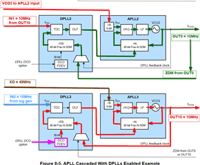
This is the idea that we have in mind --- since, if we understood correctly, activating ZDM prevents us from adjusting the frequency (both because the GCD between the input and output frequency will not be the input frequency anymore, and because the phase lock would prevent the output to change in frequency):
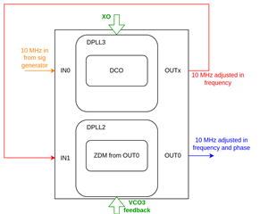
In the diagram OUTx is any output (we have chosen OUT4) and gets fed back to IN1 (avoiding this external loopback would be great, but we have found no way to internally loop back the frequency-adjusted signal).
We have a couple of questions:
1. In the IN1 field of TICS Pro we have set 10 MHz as input frequency but, given that the frequency is altered on the fly by DPLL3, it will not be 10 MHz (or, at least, not the same "10 MHz" that is present on IN0). We assume that the value given here is just to set the different DPLL/APLL parameters and, given that DPLL2 only has to output a signal with the same frequency as the input, it will not complain. Is this correct?
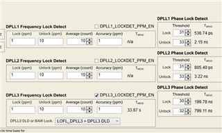
2. We have created the following configuration:
desired_config.tcs
The board, however, does not lock...
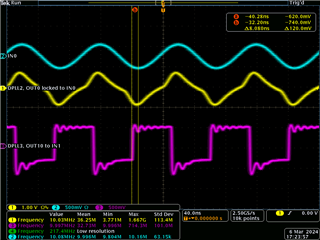
Here is what we can see on the scope (1: 10 MHz input from signal generator, 2: OUT4_P, 3: OUT4_N, M1: math function (green-blue), 4: OUT0):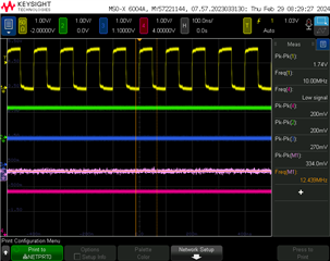
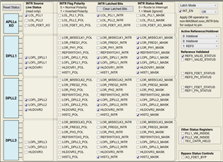
The status gives this (confirming what we observe):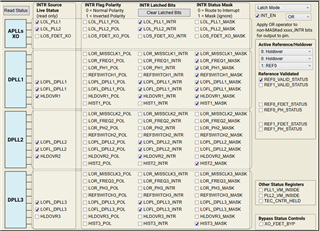
What are we doing incorrectly?
Thanks a lot in advance and best regards,
Rob


