Other Parts Discussed in Thread: LMX2592
Hi Team,
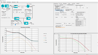
Could you please you help my customer to check what is the correct setting if they just wanted to look at this range of frequency.
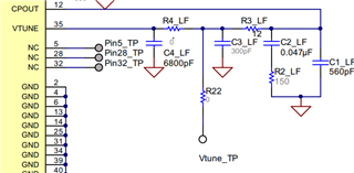
I understand that the Loop filter on the Evaluation board is fixed. So with this current Loop Filter. how to optimise the phase noise to the Best.
My VCO output is
(a) 3357Mhz,
(b) 3817Mhz,
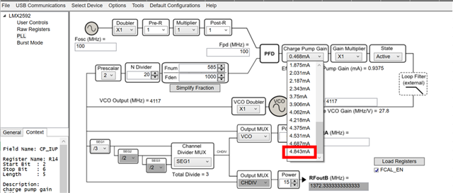
(c) 4117Mhz,
(d) 4257Mhz
(e) 4507 Mhz,
Best Regards,
Ernest