This thread has been locked.

If you have a related question, please click the "Ask a related question" button in the top right corner. The newly created question will be automatically linked to this question.

NE555: RESET pin sinking a lot of current

Part Number: NE555
Other Parts Discussed in Thread: LMC555, TLC555,

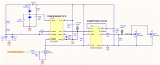
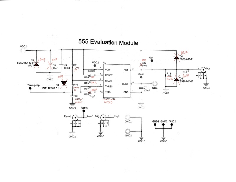
We using an NE555PWR chip (+ another IC) in a simple design to turn a momentary button into a latching button with a 2 second cooldown period between button presses. See attached condensed schematic.

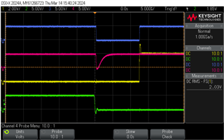
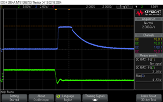
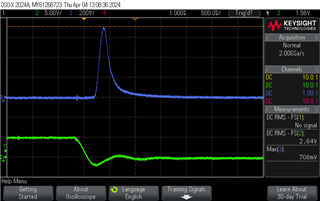
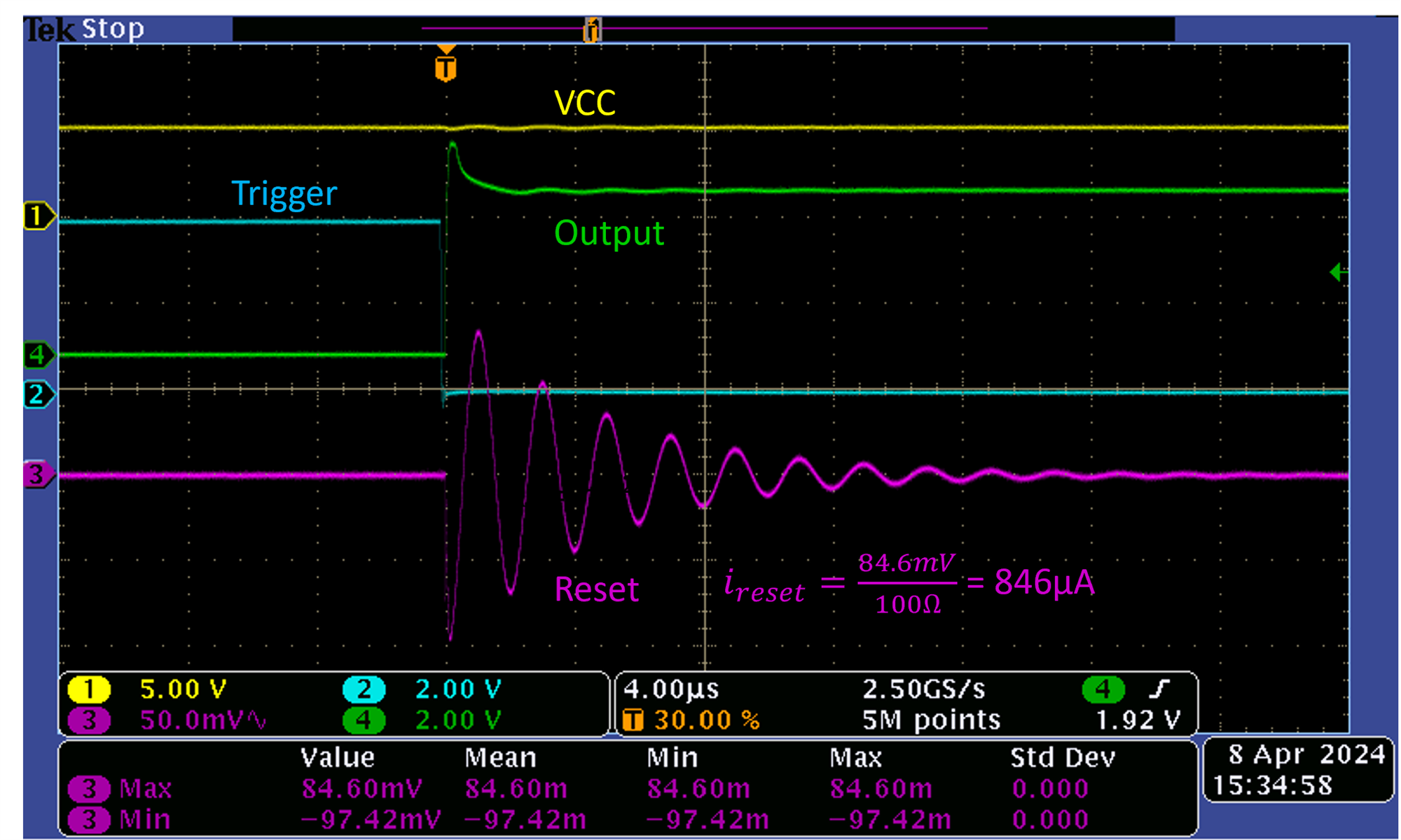
We have found that the RESET line is being pulled low momentarily by the RESET pin when the button is pressed, even though there is a strong 5V pull-up present. This causes further downstream problems. We have replaced the part with a Philips NE555N and the issue goes away; that is to say the RESET pin does not sink large amounts of current momentarily.

We have tried multiple NE555PWR chips, and multiple boards. There are no power issues present. We have removed the FET Q402 and IC U404 from the circuit, leaving just the U406 555, and still the RESET line is pulled low momentarily by the U406-4 RESET pin. Voltage levels are not being exceeded. 

We would like some help investigating why this issue is occurring please.

 
  • I have attached a screenshot from my scope depicting the behavior we/re seeing.

    Image: Green = button press, Yellow = 555 output (555OUT), Blue = latch output (UPDATE), Red = Q402_2 (555 RESET)

    Note, this screen capture was taken with the FET Q402 removed and a 1kR in place of R4030 pullup. 

    It is clearly seen that the RESET pin of the 555 is sinking a lot of current momentarily. It has been confirmed that this is still occurring when the Latch flipflop has been removed. 

  • Hi Michael,

    Based on the datasheet spec, we expect 0.1 mA on average to 0.4 mA max when RESET is at VCC, and -0.4 mA to -1.5 mA when RESET is pulled to 0V. 

    Based on your schematic and scope shot, it looks like there is a 5V differential across R403 when the button is pressed, indicating 5mA of current.

    • Have you directly measured the current?
    • Have you tried shorting RESET to VCC and measuring Vcc and the current into RESET when the button is pressed?
    • Is Vcc also dropping during the button press? Or is it just the RESET pin?

    Best,

    Alex

  • Hey Alex,

    Thanks for getting back to me.
    • No, not yet. I will push to do that shortly
    • We have directly shorted to VCC, yes. But we have not measured the current into the RESET pin when shorted
    • No, VCC is rock solid. There are no issues with power supply to the chips
    Cheers,
    Michael
  • Hey Michael, 

    We will wait for feedback from the test result on the current measurement and go from there. Thank you for taking the current measurement. 

    Best Regards, 

    Chris Featherstone

  • Hi Chris,

    I have replaced R403 with a 1kR resistor to measure the current sinking through the 555 RESET pin (note I have already confirmed the Q402 FET is not sinking current, nor is U404-6 SN74LVC CLR pin, by completely removing them on a separate board with the same result).

    The image below shows the voltage across the 1kR R403 using a low voltage diff probe. Green = button press, Blue = VR403

    You can see above that when the button is pressed, the voltage over the 1kR R403 clips at 4.58V and maintains this voltage for approx. 2us. Calculating the current through 1kR R403 (and therefore the current sinking into the RESET pin) is 4.58V/1kR = 4.58mA.

    NOTE: this current is clipped by the 1kR resistance, as seen by the flat top of the impulse waveform.

    I then replaced 1kR with 100R and captured the waveform again. The image below shows the voltage across the 100R R403 using a low voltage diff probe. Green = button press, Blue = VR403

    You can see above that when the button is pressed, the voltage over the 100R R403 rises to a maximum of 708mV. There doesn't seem to be any clipping on this impulse waveform. Calculating the current through 100R R403 (and therefore the current sinking into the RESET pin) is 708mV/100R = 7.08mA.

    The datasheet of the NE555PWR says that this current should never exceed 4mA, however I have shown that we are experiencing over 7mA of current sinking through the RESET pin.

  • Hey Michael,

    Thanks for those measurements. We’re building up a board to replicate your circuit and see if we can reproduce the issue on our end.
    We should have measurements back to you by end of business on Monday.

    Regards,

    Alex

  • Hey Michael, 

    We have built up an equivalent circuit on our EVM. The results below show that we are seeing a transient current of 846uA. We are unable to replicate the 7mA seen on your setup. We are using a function generator for the trigger pin. This would be the difference between our setups. Have you tried using a CMOS device such as the TLC555 or LMC555? If this current is affecting the application the CMOS gates would not experience this current flow since there isn't a BJT base. 

    Best Regards, 

    Chris Featherstone

  • Hi Chris,

    Thanks for getting back to me with this testing.

    Can you please provide a schematic of your exact setup?

    We have tried other TTL 555 devices and found they don't exhibit this characteristic in the same circuit. CMOS devices are likely to see an improvement here too. It seems our only option is to change parts from the NE555PWR.

    Cheers,

    Michael

  • Hi Michael,

    Below is the schematic of the setup we used.

    • In place of the physical button, we used a HP33120A function generator producing a 100 Hz, 4Vpp square wave with 2V DC offset as the input to the trigger pin. 
    • Keysight DC power supply set to 5V with a current limit of 100 mA.
    • The oscilloscope we used is a Tektronix DPO3054

    Regards,

    Alex Curtis

  • Hey Alex, can you please change the function generator output to a 0.5Hz signal and re-test? This will be more alike to a human pushing a button.

    I noticed during my testing the current sinking into the RESET pin wasn't consistent, and no pattern or correlation could be determined as to why the inconsistency occurred. Can you please capture multiple waveforms and see if there is a difference in the current you're seeing sink into the RESET pin?

  • Hi Michael,

    The scope plot we sent previously was taken with the scope in averaging mode with 16 averages. Regarding the frequency of the trigger input, lowering the frequency of the function generator to 0.5 Hz did not impact the behavior of the RESET pin. This time I used a scope with active probes which is likely why the max voltage of RESET is lower than it was before. 

    I_reset = 66.94mV/100 = 669 μA

    As we’ve discussed previously, I recommend using a CMOS based device instead of the NE555. 

    Cheers,

    Alex Curtis

  • Hey Michael,

    We looked at your first scope plot again and noticed that the trigger pin is going far below ground when the button is pressed. We went back in the lab today and pulled the trigger pin about 800mV below ground in our test setup, which caused more current to sink into the RESET pin than we measured previously. This violates the absolute maximum rating of the part.

    Kind regards,

    Alex Curtis

  • Hey Alex, 

    Good catch, that's an interesting result. We will investigate the cause of this.

    Cheers,

    Michael