This thread has been locked.

If you have a related question, please click the "Ask a related question" button in the top right corner. The newly created question will be automatically linked to this question.

LMK04832-SP: LMK04832-SP

Part Number: LMK04832-SP
Other Parts Discussed in Thread: LMK04832

Now we are developing a navigation payload.

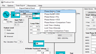
When we receive a 10.23MHz clock with a jitter of +/- 2nsec, we'd like to clean the clock using a dual PLL scheme.

We use an output clock of 122.76MHz (12 times  10.23MHz).

Could you suggest how much the 10.23MHz clock can be cleaned from +/- 2ns?

Best regards

Jae-Heung Yeom

  • Jae-Heung,

    In dual loop mode the output jitter will not actually depend on the input jitter, as the phase is taken from the input signal.  Instead the output jitter is mostly derived from the PLL2 VCO.  The datasheet gives these examples for expected output jitter. 

    Because you will have to divide down from a GHz level VCO frequency there will be some added noise from the dividers.  On a quick simulation with PLLatinumSim, our PLL simulation tool shows that you could expect a ~ 113 fs output.  

    Regards,

    Will

  • Hi Will

    Thanks for your kind response.

    I have some questions. First I don't understand why the output jitter will not depend on the input jitter, as the phase is taken from the input signal.

    Could you explain what it means that the phase is taken from the input signal?

    Do PLL2 VCO mean internal 2nd VCO?

    When you run PLLatinumSim, do you neglect input jitter?

    When disabling the input jitter, I obtained 129.3 fs. Is it right?

    Regards

    Jae-Heung

  • Jae-Heung,

    • In dual loop mode the first PLL will act as the jitter cleaning PLL, it will lock the phase of the input to the output phase of a VCXO which has very low jitter.  This very clean VCXO signal is then locked to the second PLL to generate your final output signal.  Therefore, your input signal provides the phase, but the cleaned signal performance is derived from the VCXO you choose and the VCO in PLL2.  
    • Your jitter seems roughly right, to get the most accurate result you would first include your input jitter in the simulation for PLL1 and then use that resultant jitter as the input for PLL2 which will then generate your final simulated jitter.  Because you are using dual loop mode you know that your PLL2 resultant jitter will be very good so you can make a good estimate of output jitter without taking the the true input jitter into account.

    Regards,

    Will

  • Hi Will

    Do you mean that the phase of the input is input frequency?

    Do I need to use a very clean external VCXO? Is the jitter of external VCXO directly related to the input jitter of PLL2?

    I neglected the input jitter of PLL2 for my simulation. Do I need to consider the jitter of VCXO? 

    Could you recommend an external VCXO outputting 122.76MHz?

    Regards

    Jaeheung

  • Hello  Jae-heung,

    PLLatinum Sim very good tool to use and simulate your data and how much the LMK04832-SP will clean your data. Do note that we are using a pretty good VCXO that is the main component that will be used to clean your dirty reference.

    Do you mean that the phase of the input is input frequency?

    No, what Will meant is the physical phase of the clock. In other words, irrelevant to the frequency, where is the edge of the clock located through time. Will is mentioning achieving phase lock between the input signal to the PLL and the output of the VCXO. This means that the the input signal is going high at the exact same time as when the output of the VCXO is going high.

    Do I need to use a very clean external VCXO? Is the jitter of external VCXO directly related to the input jitter of PLL2?

    This is relative, but in general you do. If you have a pretty dirty reference (which is the case with 3ns), then the better the VCXO, the better the new phase noise curve, and therefore, the cleaner the output being fed into the second PLL. You can simulate how good of a VCXO you need in the PLLatinum Sim tool I linked above.

    You can think of it like the jitter of the output of your VCXO if you new phase noise curve (and jitter is the integral of a phase noise curve), so the input jitter to PLL2 is the phase noise curve of the VCXO you choose. Does that make sense? I would recommend looking over this PDF version of a book one of my coworkers wrote about PLL theory. You can learn more about the jitter and how a PLL cleans the jitter on Chapter 27.

    Also, these set of videos further go into detail about PLLs and how they can clean a phase noise curve.

    neglected the input jitter of PLL2 for my simulation. Do I need to consider the jitter of VCXO? 

    As I explained above, it cannot be neglected.

    Could you recommend an external VCXO outputting 122.76MHz?

    The VCXO I linked above can come in several frequencies, I would reach out to Crystek to obtain a VCXO at 122.76MHz.

    Hope this helps,

    Good luck,

    Andrea

  • Hello  Adrea

    Thanks a lot for your kind answer.

    Could I know the method I can use to simulate dual PLL using PLLatinum Sim?

    I can see only a single PLL at PLLatinum Sim.

    I want to know whether the phase noise of external VCXO is outputted or whether an internal loop filter can reduce its phase noise (or jitter).

    How much can the loop filter reduce the phase noise of the external VCXO?

    Regards

    Jaeheung Yeom  

  • Hello Jaeheung,

    You would have to simulate the first PLL first, save that waveform, and then input that waveform when simulating the second PLL. However, tying to your second question, PLLatinum Sim already considers the VCXO being inputted into the second PLL so you can do your analysis on the second PLL. Note that's assuming the VCXO you are using is the same or better phase noise curve than the one I previously attached.

    The loop filter can significantly reduce the phase noise, below is an example when maximizing the loop filter's phase noise and increase the phase detector frequency as much as possible (note that higher phase detector frequency/lower N-divider value results in better phase noise).

    Best,

    Andrea

  • Hello Andrea

    As shown below, Jitter is not required although a slew rate is required.

    Could you present the performance according to the input jitter from OSCin?

    How much can the input jitter be improved from a single PLL?

    In addition, is the output clock from dual PLL not related to the input clock jitter for dual PLL?

    Thanks

    Jae-Heung Yeom 

  • Hello Jae-Heung,

    Just wondering, have you tried using PLLatinum Sim to see the effect of the phase noise curve on either PLL? Inputting an OSCin/CLKin to that tool and seeing the results would clarify several questions for you.

    How much can the input jitter be improved from a single PLL?

    The input jitter can be improved significantly when using a VCXO (or PLL1 in the LMK04832-SP EVM). Have you tried inputting a dirty signal to PLL1 of the LMK04832-SP EVM and seeing the results?

    n addition, is the output clock from dual PLL not related to the input clock jitter for dual PLL?

    The output of PLL1 is the input to the PLL2, so yes, they are directly related. I answered this question above, let me know what exactly about responses are not clear and I can ensure to clarify those with you!

    Best,

    Andrea

  • Hello Adrea

    Thanks for your answer, however, I didn't get my desired answers.

    My questions are as below:

    1) Please present the required jitter like a slew rate (0.5V/0.5ns) as shown in the datasheet for OSCin of "single PLL", not dual PLL

    2) For "dual PLL",  how much can the input jitter be improved, or is it not related to the jitter of the output clock? 

    3) Can I put the input jitter as a simulation condition into PLLatinum Sim? 

    4) Please present how to run dual PLL Simulation

    Regards

    Jae-Heung

  • Jae-Hung,

    1) Please present the required jitter like a slew rate (0.5V/0.5ns) as shown in the datasheet for OSCin of "single PLL", not dual PLL

    For OSCin input this is the required slew rate, per the data sheet:

    For CLKin input, this is the required slew rate, per the data sheet:

    In other words, the slew rate requirement for any input to the LMK04832-SP needs to be higher that 0.15V/ns and the typical value expected is 0.5V/ns.

    2) For "dual PLL",  how much can the input jitter be improved, or is it not related to the jitter of the output clock?

    Again, this is dependent on the VCXO you use. If you are using a good VCXO, like the one I recommended from Crystek above, the jitter can improve significantly form the input to the output. The exact number can only be found either by using the LMK04832-SPEVM-CVAL board or by using PLLatinum Sim. If using PLLatinum Sim, an input phase noise curve values need to be given to the tool so it can estimate how much the jitter would improve.

    3) Can I put the input jitter as a simulation condition into PLLatinum Sim? 

    Yes

    4) Please present how to run dual PLL Simulation

    1) Do the PLL1 simulation. Select LMK04832-SP as your device and then PLL1 (ignore selection of PLL2 in pciture below):

    You need to input the phase noise data of the reference signal you are using by clicking "Load Data" as shown below. Note that I highlighted where to find the user guide and where to find the '?' which will provide more help and guidance:

    The resulting phase noise curve simulation (bottom left corner of GUI), will assume you are using a Crystek VCXO like the one on the LMK04832-SPEVM-CVAL.

    2) After you get the simulation (bottom left corner of the GUI), you need to export that data:

    3) Then, go back to "Select Device" page, select PLL2:

    ...and reload the exported data back into the PLLatinum Sim as done in Step #2. The resulting phase noise curve after this second step would be your estimate.

    Here is an example of the .txt that PLLatinum Sim will accept as the input (left column are the frequency offsets, x-axis, and right column are the phase noise value, y-axis):

    100	-97.4232652201138
    114.815362149688	-98.0212325831422
    131.825673855641	-98.6188983299491
    151.356124843621	-99.2162176236359
    173.780082874938	-99.8131389360856
    199.526231496888	-100.409603041066
    229.086765276777	-101.005541853137
    263.026799189538	-101.600877087895
    301.995172040202	-102.195518714922
    346.736850452532	-102.78936316989
    398.107170553497	-103.382291286357
    457.088189614875	-103.974165900737
    524.807460249773	-104.564829075466
    602.559586074358	-105.154098875135
    691.830970918937	-105.741765618056
    794.328234724282	-106.327587510825
    912.010839355911	-106.911285555493
    1047.1285480509	-107.492537597463
    1202.26443461741	-108.070971356708
    1380.38426460289	-108.646156255257
    1584.89319246112	-109.217593820556
    1819.70085860999	-109.784706409039
    2089.29613085404	-110.34682396135
    2398.83291901949	-110.90316847876
    2754.22870333817	-111.452835916011
    3162.27766016838	-111.994775248547
    3630.78054770102	-112.527764642134
    4168.69383470336	-113.0503850122
    4786.30092322639	-113.560991935336
    5495.40873857626	-114.057688047898
    6309.57344480194	-114.538299971004
    7244.35960074992	-115.000366681791
    8317.63771102673	-115.441150235854
    9549.92586021438	-115.857684568854
    10964.7819614319	-116.246882621952
    12589.2541179417	-116.605723592185
    14454.3977074593	-116.931536137886
    16595.8690743756	-117.222374133379
    19054.6071796325	-117.477445378257
    21877.6162394956	-117.697505081721
    25118.8643150959	-117.885084035343
    28840.3150312661	-118.044418177079
    33113.1121482592	-118.181009185106
    38018.9396320562	-118.300869000702
    43651.5832240167	-118.409631092473
    50118.7233627274	-118.511772327937
    57543.9937337158	-118.610140552551
    66069.3448007598	-118.705853639168
    75857.7575029186	-118.798502207618
    87096.3589956083	-118.886515037393
    100000	-118.967548412867
    114815.362149689	-119.038812063348
    131825.673855641	-119.097310053891
    151356.124843621	-119.140035674074
    173780.082874938	-119.164217481673
    199526.231496889	-119.167789448544
    229086.765276778	-119.15038605975
    263026.799189539	-119.115387489147
    301995.172040203	-119.073882602431
    346736.850452533	-119.051718582213
    398107.170553499	-119.100186548488
    457088.189614877	-119.306747402424
    524807.460249774	-119.79144122799
    602559.58607436	-120.666691832881
    691830.970918939	-121.968254447592
    794328.234724284	-123.623943480619
    912010.839355913	-125.499889864166
    1047128.5480509	-127.468154605587
    1202264.43461742	-129.438644148085
    1380384.26460289	-131.358459319084
    1584893.19246112	-133.200903223025
    1819700.85860999	-134.95560297586
    2089296.13085405	-136.621895932616
    2398832.9190195	-138.204670308494
    2754228.70333818	-139.711674745815
    3162277.66016839	-141.151702386256
    3630780.54770103	-142.533353518555
    4168693.83470337	-143.864220320859
    4786300.9232264	-145.150385202101
    5495408.73857627	-146.396141537632
    6309573.44480196	-147.603861367833
    7244359.60074994	-148.773956118781
    8317637.71102675	-149.904902166307
    9549925.86021441	-150.993330147294
    10964781.9614319	-152.034202055109
    12589254.1179417	-153.021118227137
    14454397.7074594	-153.946799183846
    16595869.0743757	-154.803765197025
    19054607.1796326	-155.585184135104
    21877616.2394956	-156.285784165053
    25118864.3150959	-156.902661065938
    28840315.0312662	-157.435791064931
    33113112.1482593	-157.888116256668
    38018939.6320563	-158.265187344572
    43651583.2240169	-158.574474225673
    50118723.3627275	-158.824529901786
    57543993.733716	-159.024192233104
    66069344.80076	-159.181949588713
    75857757.5029188	-159.305520259231
    87096358.9956086	-159.401634347692
    100000000.000001	-159.47597367921

    Best,

    Andrea

  • Hello Andrea

    Thanks for your quick answers.

    1) Can you present the jitter of the input clock for a single PLL, besides a slew rate given in the datasheet? 

    2, 3) We consider the jitter of +/-2nsec. How can I reflect the input jitter into the PLLatinum Sim?

      As you showed,  the PLLatinum Sim accepts the phase noise curve instead of the jitter.

    4) For the phase noise curve, what is the frequency range? 
        I know the phase noise is calculated from 12kHz to 20MHz or 100Hz to 100MHz.

    Best Regards

    Jae-Heung Yeom

  • 1) Can you present the jitter of the input clock for a single PLL, besides a slew rate given in the datasheet? 

    This is dependent on the input signal you're using, so I cannot present this to you. Again, this is dependent on what signal you're feeding to the LMK04832.

    We consider the jitter of +/-2nsec. How can I reflect the input jitter into the PLLatinum Sim?

    I attached an example .txt file above. Basically you would put the frequency offset on the x-axis and the phase noise value on the y-axis. Please open the attached file above and let me know what you don't understand from my explanation:

    Here is an example of the .txt that PLLatinum Sim will accept as the input (left column are the frequency offsets, x-axis, and right column are the phase noise value, y-axis):
    the PLLatinum Sim accepts the phase noise curve instead of the jitter.

    Jitter is the integral of phase noise curve. So they are related, and therefore the phase noise curve is needed to obtain the jitter. I would recommend watching a few videos I linked above to better understand this relationship.

    4) For the phase noise curve, what is the frequency range? 
        I know the phase noise is calculated from 12kHz to 20MHz or 100Hz to 100MHz.

    This is dependent on your system. That range is the integration bandwidth you're using on the phase noise curve to obtain the jitter. Most A&D applications use 100Hz to 100MHz to see the entire phase noise curve rather than just a portion. 12kHz to 20MHz is a typical integration bandwidth we see across industries.

    Best,

    Andrea

  • Hello Adrea

    Thanks for your kind answer.

    1) Can you present the maximum acceptable input clock jitter for a single PLL of LMK04832? 

    2) How can I map the input jitter into the phase noise curve because many curves can be generated for the same jitter amount?

    Regards

    Jae-Heung Yeom 

  • Hello Jae-heung,

    There's no maximum acceptable jitter. Any amount of jitter can be inputted into the system. Just note that the more jitter the input has, the more jitter the output will have.

    2) How can I map the input jitter into the phase noise curve because many curves can be generated for the same jitter amount?

    The input phase noise curve integrated is the jitter. So you are correct different curves can give you the same amount of jitter. I believe the way to map this is the mathematical relationship of adding more/less area on a specific section on the phase noise curve. Again, I highly recommend you watch the videos and understand more about how PLLs and jitter cleaners work before asking any further questions.

    By the way, these are your local contacts in case you want more local support: David Park (david.park@ti.com) and Sua Kim (sua.kim@ti.com)

    Best,

    Andrea

  • Hello Andrea

    For CLKin or OSCin, do I have to use a differential sinewave source?

    When inputting a differential squared wave, what happens?

    In addition, can I choose whether the wave style of the output clock is sine or squared?

    Best Regards

    Jae-Heung Yeom

  • Hello Jae-Heung Yeom,

    All the information above is in the data sheet. Please make sure to read this before asking us these questions if possible. You can also contact the people above for any basic knowledge review.

    For CLKin or OSCin, do I have to use a differential sinewave source?

    You can use either (section 9.1.3 in datasheet)

    When inputting a differential squared wave, what happens?

    What do you mean? When giving this input to the LMK04832, the part will behave as expected while the schematic is built correctly and the part is configured correctly.

    In addition, can I choose whether the wave style of the output clock is sine or squared?

    No, as explained in section 8.1.5.7. The output types possible are all square wave output types, for both single-ended and differential outputs.

    Best,

    Andrea

  • Hello Andrea

    From the Datasheet, a differential sine wave is addressed. I'd like to know whether a differential square wave is possible.

    Finally, a reference clock source that produces a differential sine wave output can drive the CLKin pins using the following circuit. Note: the signal level must conform to the requirements for the CLKin pins listed in the Electrical Characteristics.

    Regards

    Jae-Heung

  • a differential sine wave is addressed. I'd like to know whether a differential square wave is possible.

    LVDS, LVPECL, and CML are types of differential square waves.

    Finally, a reference clock source that produces a differential sine wave output can drive the CLKin pins using the following circuit. Note: the signal level must conform to the requirements for the CLKin pins listed in the Electrical Characteristics.

    This statement is correct, the 4832 can do this. Again, I would reach out to the contacts I sent above for further assistance.