This thread has been locked.

If you have a related question, please click the "Ask a related question" button in the top right corner. The newly created question will be automatically linked to this question.

LMK04828: Generating a phase-aligned 10MHz output clock

Part Number: LMK04828
Other Parts Discussed in Thread: LMK04610, LMK04832

Hi,

I am working on a project using the Xilinx (AMD) ZCU216 development kit with the CLK104 add-on card.  The CLK104 board uses the LMK04828.  

I am providing a 10MHz reference signal to the LMK chip using the J11 SMA connector on the CLK104 board connected to the CLKin0 input of the LMK.  This same 10MHz reference will be provided to another development kit as well.  The objective is to generate a 10MHz output clock form the LMK04828 across multiple boards that will be frequency and phase locked to each other.  This 10MHz output will be sent to the FPGA to drive logic that will need to be synchronized across multiple boards.

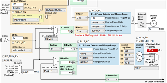
The diagram below shows how I think I need to configure the LMK chip.  Also included is the corresponding register dump file from TICS.  For now, I am using the SDCLKout11 output, which is connected to an SMA connector on the CLK104 board for easy monitoring.

CustomHexValues_ClkIn0_zerodelay.txt
R0 (INIT)	0x000090
R0	0x000010
R2	0x000200
R3	0x000306
R4	0x0004D0
R5	0x00055B
R6	0x000600
R12	0x000C51
R13	0x000D04
R256	0x01006C
R257	0x010155
R258	0x010255
R259	0x010301
R260	0x010422
R261	0x010500
R262	0x010673
R263	0x010703
R264	0x01086C
R265	0x010955
R266	0x010A55
R267	0x010B00
R268	0x010C22
R269	0x010D00
R270	0x010EF0
R271	0x010F30
R272	0x01106C
R273	0x011155
R274	0x011255
R275	0x011301
R276	0x011422
R277	0x011500
R278	0x011673
R279	0x011703
R280	0x01186C
R281	0x011955
R282	0x011A55
R283	0x011B01
R284	0x011C22
R285	0x011D00
R286	0x011E72
R287	0x011F03
R288	0x012078
R289	0x012155
R290	0x012255
R291	0x012301
R292	0x012422
R293	0x012500
R294	0x012670
R295	0x012733
R296	0x01286C
R297	0x012955
R298	0x012A55
R299	0x012B00
R300	0x012C22
R301	0x012D00
R302	0x012EF0
R303	0x012F30
R304	0x01306C
R305	0x013155
R306	0x013255
R307	0x013301
R308	0x013422
R309	0x013500
R310	0x013673
R311	0x013703
R312	0x013820
R313	0x013903
R314	0x013A01
R315	0x013B2C
R316	0x013C00
R317	0x013D01
R318	0x013E03
R319	0x013F0D
R320	0x014009
R321	0x014100
R322	0x014200
R323	0x014331
R324	0x0144FF
R325	0x01457F
R326	0x014618
R327	0x01470A
R328	0x014806
R329	0x014946
R330	0x014A06
R331	0x014B06
R332	0x014C00
R333	0x014D00
R334	0x014EC0
R335	0x014F7F
R336	0x015013
R337	0x015102
R338	0x015200
R339	0x015300
R340	0x015401
R341	0x015500
R342	0x01567D
R343	0x015703
R344	0x0158C0
R345	0x015900
R346	0x015A01
R347	0x015BDA
R348	0x015C20
R349	0x015D00
R350	0x015E00
R351	0x015F3E
R352	0x016000
R353	0x016104
R354	0x016264
R355	0x016300
R356	0x016400
R357	0x0165A0
R369	0x0171AA
R370	0x017202
R380	0x017C15
R381	0x017D33
R358	0x016600
R359	0x016700
R360	0x016819
R361	0x016959
R362	0x016A20
R363	0x016B00
R364	0x016C00
R365	0x016D00
R366	0x016E1B
R371	0x017300
R386	0x018200
R387	0x018300
R388	0x018400
R389	0x018500
R392	0x018800
R393	0x018900
R394	0x018A00
R395	0x018B00
R8189	0x1FFD00
R8190	0x1FFE00
R8191	0x1FFF53

I want to confirm that my understanding of the configuration is accurate and that I can expect the behaviour to be as I described:

  • With this configuration, should I expect the CLKin0 input and the SDCLKout11 output to be both frequency and phase aligned?
  • If I configure LMK chips similarly on different boards and provide them an equivalent 10MHz reference can I expect the SDCLKout11 outputs on all boards to be aligned?
  • Do I need to somehow trigger a SYNC event in order to get phase alignment to occur?  I saw mention of this in a different post.

I can provide additional info if needed.  Please let me know if anything isn't clear.

  • Matt,

    I will get back to you by Thursday.

    Regards,

    Will

  • Hello Matt,

    Could you attach the .tcs file? I don't believe I am seeing your correct config. I included a screenshot below of the register dump you included and what I'm seeing on my end.

    With this configuration, should I expect the CLKin0 input and the SDCLKout11 output to be both frequency and phase aligned?

    To ensure frequency and phase alignment, apart from configuring the part correctly, you need to follow a set of steps to correctly synchronize all of your outputs. I have included it below and it's also (worded differently) in p. 40.

    Steps to achieve synchronization:

    1. Need to enable SYNC circuitry to synchronize the output dividers.
      • SYNC_POL = 0, SYNC_MODE = 1, SYSREF_MUX = 0, SYSREF_PD = 0, SYNC_EN = 1.
    2. Clear local SYSREF DDLY.
      • SYSREF_CLR = 1 (forgot to mention this in the call).
    3. Enable dividers to be accepted by SYNC pulse to synchronize.
      • SYNC_DISX = 0 for all outputs needed to be synced (i.e if outputs 3 and 8 need to be synced, then set SYNC_DIS2 = 0 and SYNC_DIS8 = 0).
    4. Toggle SYNC_POL to generate sync pulse that triggers output dividers to be synced.
      • SYNC_POL = 1, SYNC_POL = 0.
    5. Disable another rising edge that comes from SYSREF to reset the output dividers.
      • SYNC_DISX = 1 (i.e from previous example, set SYNC_DIS2 = 1 and SYNC_DIS8 = 1).
    6. Release reset of local SYSREF digital delay.
      • SYSREF_CLR = 0.
    7. Set SYSREF to desired operation.
      • SYSREF_MUX = 1, 2, or 3 (2 = SYSREF pulser and 3 = SYSREF continuous).


    If I configure LMK chips similarly on different boards and provide them an equivalent 10MHz reference can I expect the SDCLKout11 outputs on all boards to be aligned?

    The same steps mentioned above need to be performed in all the chips and the SYNC pin needs to be used to achieve alignment. Basically, all boards need a common clock to base their phase alignment upon, and you would have one clock generate this clock, called SYSREF, to all the other clocks/chips. So you would have an output of on LMK04828 feed into the SYNC/CLKin0 pins of the other LMK boards. The original LMK04828 board would generate SYSREF pulser and send that pulse to the boards to trigger the peripheral boards to SYNC on the high edge of that pulse.

    This article will comment more about doing this and having multi-board synchronization. Would recommend looking at sections 2 and 3 or Section 4 for ZDM and Figure 11 + the text below it. This is also a good reference on synchronizing multiple chips on a similar part, the LMK04610. If possible, read both articles fully.

    Do I need to somehow trigger a SYNC event in order to get phase alignment to occur?  I saw mention of this in a different post.

    Correct, more information on explanation and articles above.

  • Hi Andrea,

    Thanks for the reply.  I still need to read through it in detail but wanted to provide the TICS file.  The issue may be the input frequencies - I am not sure those get reflected in the register file.  The inputs frequencies should be 10MHz for CLKin0, 10MHz for CLKin1 and 160MHz for the oscillator.

    Matt

    CustomHexValues_ClkIn0_zerodelay.tcs

  • Hello Matt,

    Is the 10MHz the clock you're sharing across your devices, correct? That 10MHz is not clocking anything else?

    Also, to clarify, your config has several outputs at different frequencies (10MHz, 125MHz, and 250MHz), is that what you want? From your description above it seems you wanted just 10MHz being fed through your system.

    Best,

    Andrea

  • Hi again.  I've read through your response and wanted to provide a bit of a higher-level system context before asking some follow-up questions.  As shown in the diagram below, multiple boards are connected through a High-Precision Timing Distribution Network and we don't have the ability to distribute signals directly from one board to another:

    Some additional notes about the design:

    • 1PPS and 10MHz signals are distributed to multiple boards through a High Precision Timing Distribution Network.
    • Assume very little offset/jitter between 10MHz references to the different boards.
    • Sync'd 1PPS signal is also distributed with this clock.
    • Inside each FPGA there is a Time of Day Counter.  These can in theory be closely synchronized between boards using the distributed 1PPS and 10MHz signals.
    • In the diagram, the 10MHz is shown going through the LMK to the FPGA and then the "regenerated" SDCLKoutY clock is used on each board to clock the Time of Day Counter.  The idea is to use the 10MHz to ensure that the TOD counter increments at the right frequency, and then the 1PPS is used to align "phase" of the TOD counter across multiple boards.
    • With locked Time of Day counters, the idea is that different boards can be instructed to generate SYNC signals at a precise moment in time.  This would result in "synchronized" SYNC signals being generated on all boards to synchronize all dividers and ensure all "other" clocks for ADC/DACs are locked across boards.  So, the SYNC signal will in theory be sync'd across boards because they all have locked TOD, but at the same time it would be generated independently by each board and not a common signal distributed to all boards.

    I am running into a few concerns about whether this will work, though:

    • In order to generate an output 10MHz to the FPGAs, it seemed like the only way to do so is using the SYSREF distribution network and an SDCLKout output.  I wasn't able to generate a clock with a 10MHz frequency on any of the DCLKout outputs (the DCLK clock dividers don't provide a large enough option for dividing down the VCO frequency to 10MHz).
    • To use the SYNC input, though, the steps involve temporarily reconfiguring the SYSREF distribution network to use the SYNC Pin to reset clock dividers.  
    • I think that when I do this, though, I would lose my 10MHz to the FPGA (when I change the value of the SYSREF_MUX), which means I would not longer have the ability to generate the SYNC signal in the FPGA.
    • I am wondering whether I can't use an LMK generated clock to generate the SYNC.

    Some more specific questions:

    • For generating the SDClkOut (10MHz) to the FPGAs, because I'm using zero-delay mode (with SYSREF feedback) and the output clock is the same frequency as the input clock, it seems I shouldn't need the SYNC signal to have these aligned across multiple boards.  Seems like the zero-delay mode handles phase alignment and that there isn't ambiguity about different phase alignments since the frequencies are the same.  Can you confirm?
    • Is it true that as soon as I reconfigure the chip to use the SYNC Pin to drive the SYSREF network that I will lose the 10MHz output to the FPGA?  If so, then it won't work to use this clock to generate a SYNC signal across multiple boards.

    Summary:

    • The high-level idea is that 1PPS and 10MHz get distributed to all boards and are used to synchronize a time-of-day counter.  The 10MHz is used as an input reference to the LMK.  All boards are instructed to generate a SYNC signal at a precise moment in time to synchronize LMK clocks across multiple devices.  But....I'm not sure the current scheme of passing the 10MHz used for TOD generation through the LMK is possible.  Maybe the 10MHz needs to go straight to the FPGA somehow.
  • Hello Matt,

    I'll get back to you by the end of next week.

    Best,

    Andrea

  • Hello Matt,

    I've read your response at a higher level, to clarify and before continuing to discuss the 4828, do you need the LMK04828 to handle a 1pps signal?

    Best,

    Andrea

  • Hi Andrea,

    The inputs I have to each endpoint are only a synchronized 10MHz and 1PPS signal from the timing distribution network (no ability to send signals between the different endpoints directly).  I want to generate locked 10MHz, 125MHz and 250MHz clocks between all endpoints.  It isn't clear to me that the 1PPS needs to go to the 4828, but at the same time, it seems to me that cross-board synchronization will require generating synchronized SYNC signals across all boards.  The 1PPS seems necessary for doing this somehow.  I think I can get sync'd 10MHz and 250MHz signals across each board without a common SYNC signal since the frequencies are all nice multiples.  But the 125MHz would require extra inter-board synchronization since it isn't a nice multiple of the 10MHz input and could end up with different phase alignments across different boards.

    Does that help clarify?

    Matt

  • Hello Matt,

    I'm talking to a colleague that knows more about handling 1pps signal so I can further assist you.

    Best,

    Andrea

  • Hello Matt,

    Read through your detailed system, thanks for all the details.

    In order to generate an output 10MHz to the FPGAs, it seemed like the only way to do so is using the SYSREF distribution network and an SDCLKout output.  I wasn't able to generate a clock with a 10MHz frequency on any of the DCLKout outputs (the DCLK clock dividers don't provide a large enough option for dividing down the VCO frequency to 10MHz).

    You are correct, that is one limitation of the LMK04828 which is why we have the LMK04832 which is pin to pin with the LMK04828. The LMK04832 can go up to 1023 on the DCLKouts and 8191 on the SYSREF divider. If 10MHz is a frequency that you must use, then the LMK04828 is not a viable option for your design.

    I think that when I do this, though, I would lose my 10MHz to the FPGA (when I change the value of the SYSREF_MUX), which means I would not longer have the ability to generate the SYNC signal in the FPGA.

    This logic is correct, so your solution would be using the LMK04832 (as mentioned above). The SYSREF signal is used as the clock that SYNCs/is the same clock provided to all your devices that need synchronization. Therefore, you would set the outputs on the LMK04832 that need to distribute this signal. Then that signal can be changed as you described in the bullet above the one I quoted above.

    I am wondering whether I can't use an LMK generated clock to generate the SYNC.

    Both LMK parts can generate the SYNC signal required to reset the dividers via SPI or the SYNC pin. This is completely up to you.

    For generating the SDClkOut (10MHz) to the FPGAs, because I'm using zero-delay mode (with SYSREF feedback) and the output clock is the same frequency as the input clock, it seems I shouldn't need the SYNC signal to have these aligned across multiple boards.  Seems like the zero-delay mode handles phase alignment and that there isn't ambiguity about different phase alignments since the frequencies are the same.  Can you confirm?

    Your 10MHz outputs using the SYSREF divider would have a phase deterministic relationship to your inputs; however, not to the rest of your outputs if you do not SYNC your dividers by using the SYSREF_MUX (as you have mentioned in one of the bullets in your response). Also, when switching to the LMK04832, 0-delay mode can only be achieved via CLKout6 or CLKout8 since you wouldn't be using the SYSREF divider anymore to generate the 10MHz clock. So at this point the only way to achieve phase alignment is via resetting the output dividers. I want to clarify too that phase alignment is not guaranteed even when the same frequencies are being outputted from the device.

    Is it true that as soon as I reconfigure the chip to use the SYNC Pin to drive the SYSREF network that I will lose the 10MHz output to the FPGA?  If so, then it won't work to use this clock to generate a SYNC signal across multiple boards.

    Yes this is true, look at one of my answers above that further explains this.

    The high-level idea is that 1PPS and 10MHz get distributed to all boards and are used to synchronize a time-of-day counter.  The 10MHz is used as an input reference to the LMK.  All boards are instructed to generate a SYNC signal at a precise moment in time to synchronize LMK clocks across multiple devices.  But....I'm not sure the current scheme of passing the 10MHz used for TOD generation through the LMK is possible.  Maybe the 10MHz needs to go straight to the FPGA somehow.

    My summary of the solution to this would be to use the LMK04832.

    Let me know if I've missed anything or if you have any other questions.

    Best,

    Andrea

  • Hi Andrea,

    Thank you for the reply.  Switching to the LMK04832 isn't really an option for us since we are using 3rd party development kits.  The info you provided is useful though.

    With this extra knowledge, I believe I've been able to remove some of the requirements that are making this difficult with the LMK04828 and come up with a solution that could work for us.

    First of all, I can get rid of the 125MHz, so can just deal with 250Mhz and 10MHz.  The 10MHz will be generated with the SYSREF DIVIDER and used for 0-delay mode feedback.  I believe that using the SYNC PIN in SPI mode (i.e. toggle SYNC_POL to reset dividers) should allow me to align the phase of a 250MHz output and the phase of the 10MHz SYSREF DIVIDER to a 10MHz input reference.  This should be deterministic since 250MHz is a multiple 10MHz (no ambiguity in terms of different possible alignments).

    If I provide the same 10MHz to a different board and follow the same SPI SYNC method I can also generate 250MHz and 10MHz clocks on that board that are aligned deterministically to the 10MHz reference. Since the 10MHz reference signals are aligned to the different boards, it can be expected that their generated 250MHz and 10MHz outputs will also be aligned (even if the SPI SYNC sequence is performed at a different time).

    All this said, the main thing is that I believe I can generate aligned output clocks (10MHz and 250MHz) using the LMK04828 across multiple boards, without actually needing to generate aligned SYNC signals to the input pin of the different devices.  Since all boards get the same 10MHz reference, and the output clocks (10MHz and 250MHz) are nice multiples of this, then SPI SYNC method run on each board should be enough to ensure all clocks are aligned to the reference.

    I'm hoping this all sounds correct to you, but if not could you comment on what doesn't seem accurate or possible?

    Thanks,
    Matt

  • Hello Matt,

    All this said, the main thing is that I believe I can generate aligned output clocks (10MHz and 250MHz) using the LMK04828 across multiple boards, without actually needing to generate aligned SYNC signals to the input pin of the different devices.  Since all boards get the same 10MHz reference, and the output clocks (10MHz and 250MHz) are nice multiples of this, then SPI SYNC method run on each board should be enough to ensure all clocks are aligned to the reference.

    I'm double checking this part with a coworker as I believe there may be an edge case that may not make this true. However, most of the time I believe it should be correct. I will get back to you with a definite answer.

    Outside of that, everything else you said it correct.

    Best,

    Andrea

  • Matt,

    All this said, the main thing is that I believe I can generate aligned output clocks (10MHz and 250MHz) using the LMK04828 across multiple boards, without actually needing to generate aligned SYNC signals to the input pin of the different devices. 

    To clarify, the 4828 will create aligned clocks, both for the SYSREF and clock outputs, and that's the SYNC signal you would be providing to each ADC/device (not the same thing as the 4828 SYNC pin).

    If this is the case, your description will only be true if you are using ZDM (0-delay mode) and the transmission lines/cables for the 10MHz need to be matched. Also, you need to make sure that SYNC signal being sent to the 4828s on your system are coming from the same device and arriving at the same time.

    Best,

    Andrea

  • Hi Andrea,

    Thanks for this and apologies for taking a while to respond!

    This helps a lot, but one more question.

    You say that the SYNC signals must be sent from the same device.  In our case, we are going to need to generate them on separate devices indepndently, put hope to be able to do it in a very synchronized way.

    My thinking is to use the Pulser Pin mode, so when the SYNC signal is asserted, the SYSREF will be driven for a programmable number of pulses.  I understand that this mode really just "ungates" the already running 10MHz SYSREF signals (which, as per our discussion above, should all be synchronized across the different boards).

    My assumption is that the LMK chip is looking for an edge of the SYNC signal and when it detects that, it will ungate the SYSREF signal at its next edge.  In that case, there might be a little bit of wiggle room when the SYNC signal could be generated in order to get the same results across multiple boards.  For example, if all boards drive the SYNC within the same 10MHz clock period window, then all board will see their SYSREF signal ungated on the same next edge.

    Maybe put a bit differently, it seems like even if the SYNC signals aren't driven at exactly the same time across all boards, if they fall within the same 10MHz SYSREF period, all boards could still see their pulsed SYSREF perfectly synchronized.

    Does that sound accurate?  

    Matt

  • Hello Matt,

    Sorry to have caused confusion. That does sound accurate. Do make sure to operate the board with 0-delay mode.

    Best,

    Andrea

  • Thanks for all your help, Andrea.  

    I believe that is all the questions I had.  I will mark this item as resolved now.  

    Matt