Part Number: LMK00304
Other Parts Discussed in Thread: LMKDB1204
Hello,
I'm working with an LMK00304 as a switch for a clock signal. The project includes two clock sources connected to Clkin0 and Clkin1 of the LMK00304 and an FPGA will control the clk select pins to chose between them.
However, once I connected everything together I noticed some glitches on the output signal that are not expected.
The goal of this system is to let a single period of one of these two clock to pass to the output, so that form the output we just see a single pulse whose rising edge is phase aligned with the input clock. To do so I'm doing the following:
- Use OSCin pin as the default clock source, this pin has a pullup resistor so that the output will be stable to 0
- Switch input to Clkin0 (or Clkin1) where a free running clock at 1 MHz is connected
- Wait one clock period
- Switch back to Oscin
Now, the issue is that when I switch the LMK00304 to the CLKin0 i observe a glitch in the output that corresponds to a voltage level in between logical 0 and logical 1. I tried both LVPECL and LVDS and see the same runt pulse in both cases. I also tried to switch between Clkin1 and Clkin0 and still observe it. Also, I noticed that this only happens then I'm swithcing from Oscin (or Clkin1) to Clkin0 and is not present when switching back from Clkin1 to OSCin (or Clkin0).
In my design it is paramount to have a clean output signal. Any suggestions on this? Is this behavior expected?
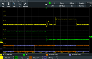
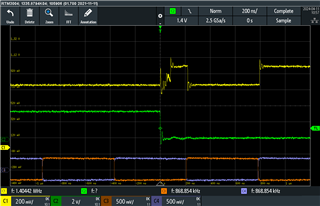
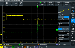
This are some screenshots of my observations,
orange and blue : differential Clkin signal at 1 Mhz. Vcm = 0 V and Vid = 700 mV
green : Clkin_sel control signal, Vlow = 0 V and Vhigh = 2.5 V
yellow : ClkoutA+
Vcc = Vcco = 2.5V
The runt pulse that appears (both if switched during the low part of the DC or the high one) is shown in the first two pictures, the third one shows that I don't see it at the output. The spikes are probably largely due to my measurement setup. The amplitude of this runt pulse is exactly half of the full amplitude and ClkoutA- is not shown but is the complementary version of ClkoutA+, so the differential voltage during the glitch is 0V.