This thread has been locked.

If you have a related question, please click the "Ask a related question" button in the top right corner. The newly created question will be automatically linked to this question.

LMK05318B: LMK05318B - Output frequency error - when using 1pps

Part Number: LMK05318B

PLC_LMK_V3 WIP.tcsPLC_LMK_V_0_0_2.tcs

Fitted LMK power modification and re-tested board. LMK clock issue still exists.

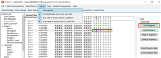
Used TICSPro v1.7.7.2 to capture state of LMK05318B. Added 4 captures to this ticket from board S/N 037 in the process of powering up as follows:

  1. LMK powered up with no PRIREF or SECREF. 10MHz out is OK.

  2. PRIREF applied. LMK exited holdover. 10MHz out went to wrong frequency

    1. R14, R20, R123, R167 & R411 changed value

  3. PRIREF removed. LMK back into holdover. 10MHz out recovered

    1. R14, R123, R167 & R411 changed value

  4. PRIREF reapplied. LMK locked. 10MHz out is good

    1. R14, R167 & R411 changed value

I’ve just added a video showing the 10MHz out for steps 1 & 2 above.

Note: R161 & R162 were dynamically changing all the time.

Note: The original programming file was generated under the older TICSPro V1.7.5.7, and the release notes indicate there have been many improvements made to the LMK05318B profile since then.3. PRIREF removed. LMK in good state. R161 and R162 dynamically changing.tcs4. PRIREF reapplied. LMK in good state. R161 and R162 dynamically changing.tcs1. PRIREF absent. LMK just powered on. LMK in good state. R161 and R162 dynamically changing.tcs2. PRIREF applied. LMK in bad state. R161 and R162 dynamically changing.tcs

  • Email set 24/04/2024: 

    Hi Jennifer,


    1. Can you please make an e2e post and try uploading the video & files there? Let me know if you still have issues and I can find an alternative method [PH: Will do]
    2. Are you using the EEPROM?  [PH: Yes do]
    3. Which steps do you follow?
      1. Option A [PH: Operates as per description]
    1. Program EEPROM
    2. Toggle PDN/power reset board with no 1PPS present
    • Still no 1PPS present à OK
    1. Apply 1-PPS à not OK
    2. Remove 1-PPS à OK
    3. Apply 1-PPS à OK
      1. Option B [PH: Operates as per description]
    1. Load .tcs file
    2. Issue a software reset (R12[7]) with no 1PPS present
    • Still no 1PPS present à OK
    1. Apply 1-PPS à not OK
    2. Remove 1-PPS à OK
    3. Apply 1-PPS à OK
      1. Other ?
    1. How do you define “wrong frequency” for the 10MHz output? Is it by measuring on the frequency counter? Checking the input to output phase relationship? [PH: We using a spectrum analyser - 10MHz drops to 9.994MHz – we are not looking at phase, this is not a requirement]

    A bit more information from today:-


    Looking at register R123:-


    0xA8 = Good (Nice 10MHz prior to 1pps)

    0x88 = Bad (Not nice 10MHz once 1pps applied)

    0xA8 = Good (Once 1pps is removed)


    One thing that we are pondering, how is the tuning word history provided for that first instance when 1pps is applied, LOFL is good and IC is out of Holdover?>

  • Thank you, Paul for uploading this from the email to e2e. We will review.

    Regards,

    Jennifer

  • Hi,  

    Very important find by Simon:--

    He debugged register by register and arrive at a config that passed (no 10M jump)

    Working with :R260 register  Bit4 appears to affect the operation '0' Fail - '1' - Pass

    We still need to prove the chip is in lock - even though LOFL is low.

    What is R260 Bit4 doing? 

    Some further questions:-- 

    What does R267[7:4] do? Its set to 0b1010 but datasheet says reserved, leave as 0b0000. Causes APLL1 to jump around every 1S when disciplining to 1PPS.

    R222 is called REF0_HOLD_CNTSTRT_BY2 in the register list, but contains PRIREF_FREQ_DET_10.

    Files attached for FAIL: PLC_LMK_V3 WIP

    FAIL: PLC_LMK_V3 WIP - with potential fix

    Thankyou 

    5277.PLC_LMK_V3 WIP.tcsPLC_LMK_V3 WIP - with potential fix.tcs

  • Hi Paul,

    R267[7:4] are reserved as it is IP related and also not for modification. They are internally updated by TICS Pro when config is configured.

    R222, the register name is REF0_HOLD_CNTSTRT_BY2; the register field is PRIREF_FREQ_DET_10.

    I will check the files with 1PPS input to confirm the output reading.

    -Riley

  • Hi, is there any update from your previous response? We have two files - one works and one does not. R260 bit 4 plays a major part in this '0' for  fail and '1' for pass. Above all, this is the area that we would like a response to. Out firmware needs to be committed next week.  Thanks Paul

  • Hi Paul,

    I've tested with both files and can see the outputs lock with correct frequency (10MHz).

    Note that with 1PPS input, the lock time is longer compared to 10MHz input. When the input is present, it will be validated, once PRIREF_VALSTAT = 1, the device would start locking and clear LOFL & LOPL. With 1PPS, LOPL is clear at a slower rate than LOFL (a few mins) and during this time, it might experience frequency drifting on the output, but once it locks (LOPL =0, LOFL =0), it would be at correct output frequency.

    The current setting has 1PPS phase detector at 2.46us which also accounts for XO ppm error. Perhaps the total ppm error from XO and input are higher than this threshold so the device couldn't clear LOFL, LOPL. You could try supply XO and 1PPS from the same source to minimize this total ppm error so the input can stay within the phase detect threshold to clear LOPL.

    -Riley

  • Hi Riley, Thankyou for the response. We have a fixed 12.8MHz oscillator and the 1pps on SEC/PRI come from external modules. Maybe on this brd our OSC is slightly out in terms of ppm?... The other major point is the R260 register - this appears to solve our issue but we don't know why..

    Thankyou Paul

  • Hi Paul,

    R260[4] is DPLL_TDC_SW_MODE is to control TDC rate through software, but we don't adjust any TDC rate. In either case, the device should lock.

    -Riley

  • If you follow the attached configuration files 1, 2, 3 & 4 which were captured chronologically showing the state if the LMK as 1PPS is applied, removed and reapplied you can see that register R123 changes from 0xA8 to 0x88 in the failing state. This corresponds to PLL1_NUM_STAT changing from the correct value of 0xA800000000 in the good state to 0x8800000000 in the bad state. i.e. a single bit change.

    Changing the APLL1 fractional divider numerator by such a large amount changes the APLL1 divide ratio from 97.65625 to 97.53125. With a 25.6MHz reference, the PLL1 VCO is disciplined from 2.5GHz to 2.4968GHz (i.e. approx. -400ppm) which is beyond the APLL1 VCO pulling range so it looses lock.

    When 1PPS is first applied, it is a few seconds before PRIREF_VALSTAT changes from 0 to 1 (as expected). A few seconds later, HLDOVR changes from 1 to 0 (as expected). A few seconds later LOFL_DPLL changes from 1 to 0, indicating that the DPLL is locked in frequency. The problem occurs always 5 seconds after this point, causing the APLL1 VCO to go off tune and LOFL_DPLL to change back to a 1.

    Why is the DPLL getting the wrong value of PLL1_NUM_STAT when it first tries to discipline to 1PPS?

    State

    1 – Initial powerup. No 1PPS on PRIREF

    2 – 1PPS applied to PRIREF

    3 – 1PPS removed

    4 – 1PPS reapplied to PRIREF

    10MHz out

    Good

    Bad

    Good

    Good

    R14

    0xF0


    LOPL_DPLL=1

    LOFL_DPLL=1

    HIST=1

    HLDOVR=1

    0xC0


    LOPL_DPLL=1

    LOFL_DPLL=1

    HIST=0

    HLDOVR=0

    0xF0


    LOPL_DPLL=1

    LOFL_DPLL=1

    HIST=1

    HLDOVR=1

    0xA0


    LOPL_DPLL=1

    LOFL_DPLL=0

    HIST=1

    HLDOVR=0

    R20

    0xF0

    0xF8

    0xF8

    0xF8

    R123

    0xA8

    PLL1_NUM_STAT=

    0xA800000000

    0x88

    PLL1_NUM_STAT=

    0x8800000000

    0xA8

    PLL1_NUM_STAT=

    0xA800000000

    0xA8

    PLL1_NUM_STAT=

    0xA800000000

    R167

    0x00

    0x01

    0x00

    0x01

    R411

    0x00

    PRIREF_VALSTAT=0

    0x04

    PRIREF_VALSTAT=1

    0x00

    PRIREF_VALSTAT=0

    0x04

    PRIREF_VALSTAT=1

    P.S. Is there a more up to date programming manual for the LMK05318B? The register programming manual (Rev A) on the TI website, dated April 2021, seems to list all the registers twice, with lots of inconsistencies between the two lists, and doesn't really explain what the registers do.

  • Hi Simon,

    PLL1_NUM_STAT is the live update of PLL1 numerator value. It changes according to DPLL input frequency to tune VCO. I couldn't duplicate to the issue where R123 changes to 0x88. Is the 1PPS source noisy? It could detect the wrong rising edge of the signal.

    The programming manual is being update. It would have one table for device registers and another one for EEPROM map. We will include some more description to the registers but shouldn't have significant change on the register names or functions.

    -Riley

  • Hi Riley,

    The 1pps signal is derived from a clean GPS receiver module.

    It appears that the device is not operating as intended, with may possibly have to concess the use of 1pps on either PRI/SECREF, this would mean that we are operating in holdover at all times.

    This is Not the reason why we chose this device!!.

    The behaviour that we would expect is as follows:-

    1) Device powers up in free-run

    2) Then holdover

    3) PRI/SEC valid [Numerator is seen to change]

    4) Some time after Frequency lock acheived. [Numerator is steady]

    5) At any time after if PRI/SEC go INVALID - HOLDOVER is reached [Numerator is seen to change]

    6) PRI/SEC go VALID - Frequency Lock is reached  [Numerator is steady]

    Would it be possible to check his behaviour on your card please?

    A telecon would be greatly appreciated.

    Thankyou Paul

  • Hi Ryan,

    We have just used the LMK05318BEVM card with the file attached, and seeing some very strange behaviour that could be linked with the original issue.

    The device is designed to be disciplined from a 1pps source, in the event that the source disappears, the disciplining stops, when the 1pps re-appears, disciplining continues. This is not happening, either on our card or the TI EVM card.

    We are monitoring this via PLL1_NUM_STAT in 'User Controls'.

    1) At power on - the value is fixed

    2) with 1pps valid the value waivers

    3) 1pps removed the value is fixed

    4) 1pps re-applied the value is fixed {should be trying to discipline}0385.PLC_LMK_V3 WIP.tcs

    Maybe there is an error in our file, but all we want to do is get the device to discipline from either PRI or SECREF when they re valid. Currently, running in Holdover is our only method (despite the device telling us that its out of Holdover and F locked).

    Please try this at your end, as we now see it on TI's evaluation board.

    Thanks Paul

  • I have found, by fiddling with raw bits, that if I set R252 bit 6 to a zero then the behavior is more like we would expect.

    This bit is described as DPLL_ZDM_NDIV_RST_DIS. What does it do?

    I do not require ZDM as I no longer need to sync the 1PPS of OUT7 to the 1PPS reference. How do I control ZDM mode in the GUI V1.7.7.2? 

    I can see PLL1_NUM_STAT jump around (+/-300000) from its nominal value when the 1PPS on PRIREF is first applied, then stay at a fixed number when 1PPS is removed, then jump around again when 1PPS is reapplied, but only by +/-1.

    Why is the DPLL adjusting the APLL1 by so much on the first time it sees 1PPS, and so little the second time it sees 1PPS?

    Have you managed to duplicate this on the TI evaluation board?

  • Hi Simon & Paul.

    Sorry for the delay.

    I've reloaded the config and noted on ZDM bits are enabled while PLLx_Px_SYNC_EN = 0. You should be able to disable ZDM through Raw Registers page on GUI by writing direct 0/1 to the bits, R252.

    You might want to disable Auto Update so the bit isn't updated while writing. After all bits are written, do Write Register to update.

    As PLL1_NUM_STAT is updating to lock to 1PPS, we expect there is some change to PLL1_NUM_STAT, but not at +/- 300000
    From the files you provided, I did not observe this railing. I will start from a different config to duplicate this issue.

    -Riley

  • It was the raw register write that I used to change the bits and observe the behavior. However. I am concerned that there may be other bits in the configuration that need changing that the GUI is not controlling. Control for ZDM mode was in an earlier GUI, but appears to have been removed in V1.7.7.2.

    There are a lot of reserved register bits that are set to a state that are different to the default given in the register map document. Is there a newer document that states what the reserved bits should be set to?

    The roughly +/-300000 change I was seeing in PLL1_NUM_STAT only corresponds to a small ppb change in output frequency. What range of numbers are you seeing when you first apply 1PPS, and what range of numbers do you see if you remove 1PPS and reapply it a second time?

  • Hi Simon,

    Majority of the team is OoO for business travel and I'm fully occupied at this time. I have addressed this concern to our internal team to duplicate. Please allow us sometime to get to this.

    -Riley