This thread has been locked.

If you have a related question, please click the "Ask a related question" button in the top right corner. The newly created question will be automatically linked to this question.

LMX2594: Inconsistent VTUNE for output freq.

Part Number: LMX2594

Hi, 

I'm mesuring VTUNE pin of the eval-board LMX2594EVM and I found the VTUNE voltage mesured on scope is inconsistent to the expected values.

In fact, I would like to generate a linear sawtooth ramp from 5GHz to 5.025GHz (so VCO from 10GHz to 10.05GHz). The chip lock @10GHz with VTUNE=1.32V.
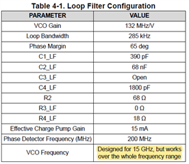
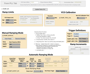
The settings are: 

So for ramps from 10GHz to 10.05GHz, I was expecting the VTUNE varies from ~1.32V to 0.85V (voltage verified without ramp and calibration).

However I observed 2 cases:

- With VCO_CAPCTRL_FORCE=1, VCO_SEL_FORCE=1 and VCO_DACISET_FORCE=1 (VCO_SEL, VCO_CAPCTRL and VCO_DACISET values read back from the locked state @10GHz), the VTUNE variations are consistant:

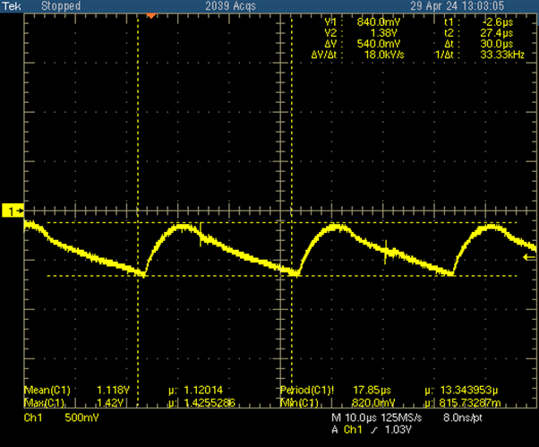
  VTUNE between 1.38V and 0.84V --> OK

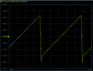
- But without forcing VCO_SEL, capcode, etc, the ramp on the spectrum analyser is OK but the VTUNE variations on the scope are inconsistent to expected values:

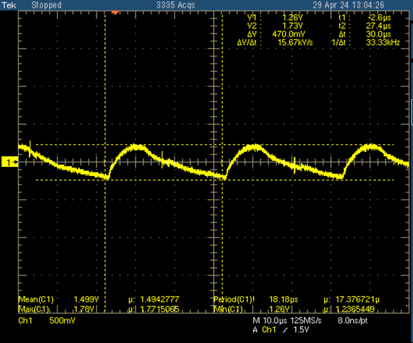
  VTUNE between 1.73V and 1.26V --> NOK

In terms of calibration free bandwith for this frequency @10GHz, I also generated a ramp from 10GHz to 10.01GHz and I got the similar results. 

Another observation is: with forced settings, the lower freq. boundary of the ramp is lower than that without forced settings:

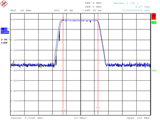
 Black: FORCE=0; Blue: FORCE=1 (VCO, CAPCTL and DACISET)

My question:

- Why I need to force VCO settings in order to get a consistent variations of VTUNE? The chip is not calibrating in my case I think....

THanks for your help.

XL

  • Hi XL,

    RAMP_EN bit and FCAL_EN bit are both located in the same register address. So whenever we enable ramp, the device will also run a VCO calibration. Therefore, it is normal that you have got a different Vtune voltage with and without forcing the VCO parameter, as the VCO_CAPCTRL value may be different.

    The wider modulated bandwidth is due to your ramp configuration. Since you reset the ramp at the beginning of each RAMP1, there may be an overshoot, so the modulated frequency range is wider than your expectation. We need a test equipment capable of measuring frequency vs time to clearly see the problem. An example plot as below.

    BTW, what is your loop filter bandwidth?

  • Hi Noel,

    I checked the read back before and after ramping at the start freq. (i.e. @10GHz), the capcode is always the correct one...

    Why duing the ramping the VCO calibration choose a different capcode at the beginning (i.e. 10GHz)? Is it OK to ignore this despite that the VTUNE is not the correct one (or the Capcode is not the same as the case for single tone freq. calibration)? Is there a way to find this different capcode?

    If I indeed need the correct value of the VTUNE to indicate that the ramping functions well, should I or could I use FORCE feature? 

    The default loop filter on the EVM board is used:

    Is there a detailed relationship between loop BW and the overshoot/undershoot of freq. ?

    Thanks

    XL

  • Hi XL,

    Forcing the VCO parameter in ramp mode is not an expected mode of operation, I don't have any data to provide an answer to you. Also in ramp mode, I only care the frequency rather than Vtune, I did not notice that Vtune is different from the static state. I would say if frequency is correct, even though Vtune is different from static state, it should be fine. 

    There is no equation to correlate the overshoot and the loop bandwidth. Simply speaking, we need a very wide loop bandwidth to reduce the overshoot.