This thread has been locked.

If you have a related question, please click the "Ask a related question" button in the top right corner. The newly created question will be automatically linked to this question.

LMK05318B: Unclear status bit description

Part Number: LMK05318B
Other Parts Discussed in Thread: LMK5B12204,

Tool/software:

We have problems to lock the DPLL. During debugging we are constantly struggling with the available documentation. Can you clarify (and hopefully update) the documentation and SW?

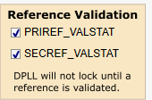
TICS Pro shows 

and
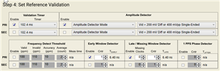
In the manual there is
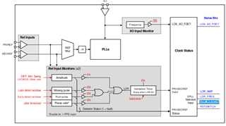
  1. LOR_MISSCLK is not described
  2. All LOR_ seems to be something different than the reference validation settings from TICS Pro. I've already asked for clarification here https://e2e.ti.com/support/clock-timing-group/clock-and-timing/f/clock-timing-forum/1370833/lmk5b12204-non-working-lor_missclk-lor_freq-and-lor_amp-in-tics-pro
  3. The "Frequency detect threshold" is missing in the block diagram
  4. Is jitter Threshold the 1 PPS Phase detector?
  5. How can LOR_ work if the information is ORed away?
  6. How are the PRI/SECREF_VALSTAT generated?
    1. There's no documentation in the manual
    2. Missing in the register description of LMK5B12204
    3. Added in the register description of the LMK05318B. But this guide contains duplicated and misleading information which is already mentioned in multiple threads like https://e2e.ti.com/support/clock-timing-group/clock-and-timing/f/clock-timing-forum/1075093/lmk05318b-registers-programming-manual-for-lmk05318b
  7. The "DPLL Frequency Lock Detect" can be disable. But the corresponding register is not described
  8. Is there an enable for the "DPLL Phase Lock Detect" like all other detectors?
  • Hi Christian, 

    Thanks for reaching out, we will get back to you in the next day or two with some clarifications about these status bits. 

    Regards, 

    Connor 

  • Hi Christian, 

    Sorry for the delayed response here, see my feedback below: 

    1. and 2.  See my comment in the other thread here: https://e2e.ti.com/support/clock-timing-group/clock-and-timing/f/clock-timing-forum/1370833/lmk5b12204-non-working-lor_missclk-lor_freq-and-lor_amp-in-tics-pro 

    3. Thanks for the feedback, I'll bring this up with the team for the next revision of this datasheet

    4. Correct, Jitter threshold / Phase Valid in this diagram is referring to the 1PPS phase detector in TICS Pro 

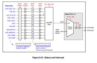
    5. Can you explain a bit more what you mean by this? The AND or OR logic for the interrupt signal determines how the STATUS pins behave when Interrupt (INTR) is chosen for STAT0/STAT1_SEL. Here's a block diagram of the status and interrupt logic in case it helps:

    6. PRI/SECREF VALSTAT indicate if PRIREF/SECREF have been successfully validated, i.e. frequency detect threshold, early/late window detector, and amplitude detect are all valid for the duration of the validation timer. However, you are correct that this field is missing in the LMK5B12204 programming guide and is only in the LMK05318B. I can bring this up to the rest of the team the next time we update this documentation. 

    7. DPLL frequency lock detect is described on the "Set DPLL (cont.) page of the TICS Pro wizard. The DPLL is considered to be frequency locked if the frequency error between the VCO1 and the references is within the lock threshold

    8. The DPLL phase lock detect is always enabled, however this should only affect the LOFL_DPLL bit on the status page. 

    Let me know if you have any other questions. 

    Regards, 

    Connor