This thread has been locked.

If you have a related question, please click the "Ask a related question" button in the top right corner. The newly created question will be automatically linked to this question.

LMX25412380EVAL: Re: LMX25412380EVAL

Part Number: LMX25412380EVAL
Other Parts Discussed in Thread: LMX2541, LMX2572LP

Tool/software:

Dear Team,

I would like to generate the local oscillator signal to down-convert my RF signal to a baseband signal. My input frequency range is a maximum of 80 MHz coming out from my ADC. I would like to generate the tunable output frequency and must be in phase with the reference signal. My system requires an output frequency range of 30 MHz to 800 MHz. We are flexible with the frequency resolution, for example, it can be 100 kHz or 200 kHz. However, the IC must contain all the required parts of the PLL integrated internally. In the process, I found the LMX2541 integrated all the components internally. Could you please provide some of your insights regarding my system's specifications? Will the LMX2541 support the reference clock signal from my ADC? I also would like to know about programming the dividers to adjust the output frequency. Is it achievable through the code loader from TI? It is always convenient with other alternatives as well, which you suggest. In the evaluation board of LMX2541, a few components are mentioned as open. Is it adviseable to neglect the components kept open? My concern is about the input, and output frequencies, phase noise to be below as low as possible, very less spurious, and programming the dividers. Could you  please also provide the updated schematic for the evaluation board? Thank you in advance.

Kind Regards, 
Uday Kiran.

  • Hi Uday,

    We suggest the LMX2572LP which has better performance than LMX2541.

    You can find all the resources from the product folder (www.ti.com/.../LMX2572LP), including EVM information. 

  • Dear Noel,

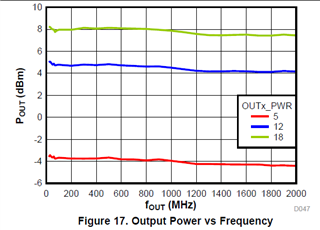
    One main consideration is the RF output signal power level of the PLL. I recently did measurements with my RF mixers. The required LO signal power level must be greater than +3 dBm. I require the output power level of the PLL to be nearly +7 dBm if possible. The main reason for considering the power level is that I need sufficient power levels to drive my mixer. As mentioned before the input frequency, in this case a maximum frequency is 80 MHz from my ADC ref clk. The output frequencies are 30 MHz to 800 MHz. In the case of LMX2572LP, the output power level is +5 dBm referred to in the datasheet. Therefore I need the output power level of the signal that is going to feed my RF mixer must be greater than +3 dBm. If am wrong regarding the output power level of the LMX2572LP. Could you please give your insights and suggest the PLL that can be able to produce the output power level from RF out must be greater than +3 dBm? Thank you in advance.

    Regards,
    Uday Kiran Chandragiri.

  • Hi Uday,

    According to the datasheet, output power can reach 8dBm. 

  • Hi Noel,

    I saw the graph, but the green curve indicates the number 18. The red and blue are 5 and 12, what does this numbering and the colour indicates? On page 6 of the datasheet, it is mentioned that the RF output power of the single-ended output is 5 dBm. I require the single-ended output. Could you please give some of your insights? Thank you in advance.

    Regards,
    Uday Kiran Chandragiri.

  • Hi Uday,

    Output power is configurable with the register OUTx_PWR, whereas x represents A or B. 

    On page 6, the test condition was OUTx_PWR = 15. 

    All RF power measurement is single-ended either from the _P or _M pin with the unused pin 50Ω terminated.