This thread has been locked.

If you have a related question, please click the "Ask a related question" button in the top right corner. The newly created question will be automatically linked to this question.

LMX2820EVM: Need some guidelines for producing frequencies above 10GHz with external VCO

Part Number: LMX2820EVM
Other Parts Discussed in Thread: LMX2820

Tool/software:

Hello I am interested in creating a frequency above 10GHz using an external VCO.  I am using the LMX2820EVM as my PFD.

My current settings are as follows:

1) PFD Comparison Frequency: 250MHz

2) External VCO is connected to the RF_IN port

3) Loop filter was designed for 150kHz BW with phase margin of 60 (I've characterized the external VCO to determine its kVCO and entered this into the TI PLL design tool)

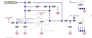
4) I've used the 3rd order Type A Active Loop Filter.  I am applying a bias voltage of 1.2V to the op-amp's non-inverting input. (0.1uF decoupling cap also installed)

5) MASH ORDER set to: Integer.  For PFD_DLY, I've tried values of 5, 6 and 7.

So on a positive note, the LMX2820 is able to lock onto the desired frequency.  However there is a lot of noise and spurs in a region 60kHz to 600kHz offset from the main tone.

Any ideas as to how this can be cleaned up.

Thanks.

  • Hi Dan,

    There is an app note regarding using an external VCO and driving it with LMX2820 - I will attach it for reference: https://www.ti.com/lit/an/snaa361a/snaa361a.pdf?ts=1717718276974&ref_url=https%253A%252F%252Fwww.google.com%252F

    Do you see these spurs on the reference?

    Can you provide your programming procedure step by step? Are you enabling all the required external VCO mode usage bits? The PFD_DLY divider values are found on page 24 of DS - correct divider value is based on RFin and RFin divider value 

    Regards,

    Vicente

  • Hello Vincente,

    Thank you for providing the link to the app note.  The reference frequency does not have any substantial spurs.

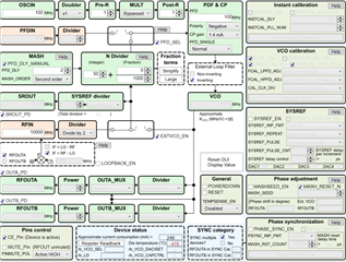
    Regarding programming sequence, I am not at that stage yet.  I am still using the TICs software to control the device.  With that said, I decided to retrace my steps through the TICs GUI.  What I found was that I can only get the external VCO locked by first setting things up to use the internal VCO and pushing the calibrate button.  Then I switch to use the external VCO.  So I suspect I might not be using the TICs software 100% correctly and that some of the internal VCO settings are retained.

    Thanks,

    Dan

  • Hi Dan,

    Please try use attached configuration, simply load the .tcs file and then Ctrl+L to load all the registers to the EVM.

    2820_extVCO.tcs

    Are you using the onboard placeholder active filter?

    When we hook up the EVM and an VCO board together, quality of wiring is very important, make sure to use shielded cable for Vtune or CPout. 

  • Thanks Noel,

    I will try the register file shortly.  Regarding your question about the loop filter.  No we are not using the on-board place holder for the active filter.  We are using an external PCB module for that.  We removed R28 and populated R29 and a couple of other components to bring CPOUT to the SMA connector.  External to the LMX2820 board we are using shielded SMA cables in our connections to the external loop filter board and VCO.

    Thanks,

    Dan

  • Hello Noel / Hello Vincente,

    I uploaded the register file and made minor modifications to accommodate my setup.  The results were more or less the same.  I am beginning to think, however, that the spurs have more to do with the VCO than the LMX2820.  When I free run the VCO, independent of the LMX2820 I see the same 'bumps' in the phase noise at the same offsets that were observed when I was locking.  So much so, that if the free-run plot was slid down it would almost perfectly overlay the previous locked plot in this region.

    Regards,

    Dan 

  • Hi Dan,

    If the VCO is free running without a Vtune voltage and you still see the bumps, probably it is a power supply issue. Also good to double check this using a spectrum analyzer, see if you have two bumps (one at each side band) or you actually have many bumps (modulation?).

  • Thanks Noel,

    Power supply was indeed the issue.  We are now powering the VCO from a 'cleaner supply' and the 'bumps' are gone.  So issue is resolved.

    Thanks again,

    Dan