NE555: pwm jitter

Part Number: NE555
Other Parts Discussed in Thread: TPS73250-EP

Tool/software:

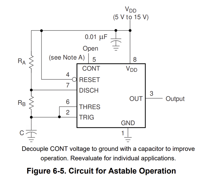
Hello, I'm building a measurement circuit based upon the NE555 chip working in astable configuration.
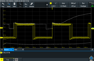
I am bothered with duty cycle jitter on the output of about 70us on a 1811us pulse length.
Could you explain the reason and if possible propose a (or some) solution(s) in order to further reduce this?

Looking out to your reply,

Thanks!

  • Hey Marc, 

    I have see this a lot working/supporting timers myself and this looks like either scope settings such as trigger settings or the reset pin is possibly floating. An unrelated additional side note I would check is that the scope probe is calibrated. Calibrating the scope probe should make the waveform more square. 

    Best Regards, 

    Chris Featherstone

  • Hi Chris,

    Thanks for the reply.
    I've checked your comments:
    1). The scope is triggering at the upcomming slope of the signal and the trigger level is set properly.
    2). The reset pin is connected to Vcc (decoupled with cap to Gnd)
    3). Scope is quite new and calibrated

    Do you have any other suggestions?

    Thanks, Marc

  • Hi Marc, 

    Can you provide a schematic of your circuit? What frequency of operation is the timer configured for?

    Best Regards, 

    Chris Featherstone

  • Hi Chris,

    Sure. Please find it attached.
    The cap we use connected to trigger is between 1 - 3nF
    The frequency is important and tuned between 200Hz and 1kHz and then digitalized with dual inverting buffer to a microcontroller.

    Reg. Marc

    Scan2024-06-13_212919.pdf

  • Hi Marc, 

    This doesn't look like a standard timer configuration so I will need to simulate it to understand it. Below is the standard Astable configuration. Was the goal an Astable configuration? Is it possible that it needs the connection of threshold and trigger as shown below?

    -Chris

  • Hi Chris, 

    Thanks for your reply. 2&6 are indeed connected as well.
    Rb is tunable so we can tune the output frequency towards the mentioned range.
    Is there anything you can add to improve the signal quality?

    Reg. Marc

  • Hey Marc, 

    I am currently thinking what can be going on outside of scope settings or configuration issues. If pin 2 and 6 are connected and reset is pulled high there is no reason to see anything but a normal clean square waveform on the output. 

    A few things that could help us do a process of elimination would be to 

    • Remove the diode connected to the supply
    • Replace the potentiometer with a regular resistor
    • Remove the output connection to the additional circuitry and just test the output with no load. 

    Recreating the waveforms below with your values and show the cap charge and discharge along with the output. On the cap waveform measurements on the scope should show 1/3VDD and 2/3VDD trip points and those should align with the output waveform. A frequency measurement on the scope would be good to see also. The goal would be to isolate to a very simple timer setup and check the functionality. If the device is still showing this behavior it may be good to try a brand new device. 

    Best Regards, 

    Chris Featherstone

  • Hi Chris,

    Thanks again for the reply.

    I checked the items you mentioned but this is not the main issue. The circuitry was fed by a USB hub which seems to have a noisy power. Might need to use a proper DC-DC converter for improving the noise since we want to keep using a USB power supply. Do you have any suggestion or circuit you can recommend?

  • Hey Marc, 

    I am glad the issue was identified. Yes if the supply is noisy or moving, this can create and issue since the 2/3 and 1/3 trip points are created by voltage division from the supply down to the comparator inputs. For the lowest noise supplies you may consider looking at a linear and low dropout regulator or LDO. 

    LDO Product list:

    https://www.ti.com/power-management/linear-regulators-ldo/products.html

    If there are power limitations using an LDO then a DC-DC converter can certainly be an option. 

    Below is a link to Ti DC-DC products. 

    https://www.ti.com/power-management/dcdc-power-modules/products.html

    Depending on what device you would be interested in I can move this thread to our LDO experts or our DC-DC experts for further support on these products. 

    Best Regards, 

    Chris Featherstone

  • Hi Chris, 

    Many thanks for your reply and good support.
    We either power the NE555 seperately from the digital postprocessing using a LDO like TPS73250-EP or if we power all together we have a look for a DC/DC since we then need to power it depending on the setup between 150mA up to 2A max.
    In general, would an isolated DC/DC converter have any benefits in our situation?
    If required, you can move the thead.

    Thanks, Marc

  • Hey Marc, 

    I have moved the thread for support on the DC-DC converter side. I hope this helps resolve the issue in the application circuit. Let me know if I can be of further assistance. 

    Best Regards, 

    Chris Featherstone

  • Hi Chris,

    Thanks, I'll wait for them to reply.

    Another question is regarding temperature. We see the influence of surrounding temp/hum reflecting to the probably the cap and it is changing the output frequency. How would you advise us to compensate for these environmental efffects? Would you know a effective solution? Thanks,

    Regards, Marc

  • Hi Chris, I didn't receive any message from the DC-DC converter side. Can you check again or should I post a new question myself?

  • Hi Marc

    Sorry for missing this, what kind of DCDC converter you are looking for a buck converter?  I suggest you can start a new thread , you can specify the Vin range and the Iout needed.  let's close this thread here.

    Thanks and best regards.