This thread has been locked.

If you have a related question, please click the "Ask a related question" button in the top right corner. The newly created question will be automatically linked to this question.

TLC555: TLC555IDR

Part Number: TLC555

Tool/software:

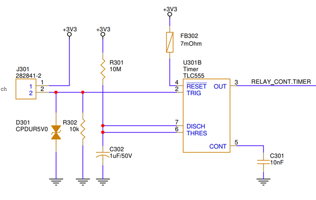
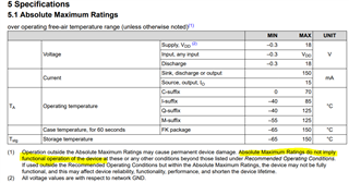
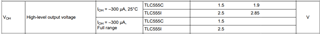
I designed a circuit using the TLC555IDR timer IC where a trigger pulse(from connector J301) switches its output high and it's output is connected to both an optocoupler and a GPIO(in a parallel sense). The optocoupler requires 5-7mA, but when connected, the output voltage drops to 1.6V, insufficient for the GPIO's high logic level. Removing the GPIO had no effect, but removing the optocoupler restored the output to 3.3V. According to the datasheet, the TLC555IDR can source up to 15mA. Could someone help clarify if my conclusion about the timer's current sourcing capability is correct?

  • Hi Darshan,

    The TLC555 timer is not designed to source a significant amount of current. The 15mA specification you are referring to come from the absolute maximum ratings table. The Abs max specifications are meant to defined short-duration stresses that will damage the device. In this case, If you attempt to pull more than 15mA from the TLC555 output, the device will be damaged. Footnote 1 of the abs max table explicitly states that these ratings do not imply functional operation under these conditions.

    If you look at the specified performance in the electrical characteristics table, you will see that the high-level output voltage is specified for an output current of -1mA (5V supply) and -300μA (2V supply).

    Often it helps to include a pull-up resistor from the timer output to the 3.3V supply which will help relax the current sourcing requirements on the timer. The pull-up resistor works because the timer is better at sinking current than sourcing current. You may also consider adding a logic buffer for your optocoupler input. 

    Regards,

    Zach