This thread has been locked.

If you have a related question, please click the "Ask a related question" button in the top right corner. The newly created question will be automatically linked to this question.

LMX1204: LMX1204 clock and sysref phase cannot be fixed

Part Number: LMX1204

Tool/software:

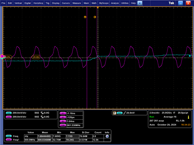
We want a fixed phase relationship between CLKOUT and SYSREF generated by LMX1204. When using LMX1204 for clock and sysref synchronization, the phase cannot be fixed.

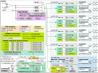
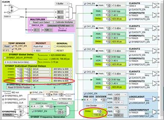
Four SYSREFOUT, one LOGICLKOUT and one LOGISYSREFOUT are generated by dividing the CLKIN of LMX1204, and four CLKOUT with the same frequency as CLKIN are generated by the buffer function.
In the current configuration, SYSREF uses the continuous mode, and SYSREFREQ has a single pulse LVDS level input through our control.

After LMX1204 generates four CLKOUTs, four SYSREFOUTs, one LOGICLKOUT and one LOGISYSREFOUT, we modify the configuration as follows:
1) Set the SYSREFREQ_N level to 1.4V, set the SYSREFREQ_P level to 1.0V
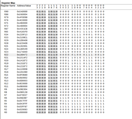
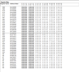
2) Modify the LMX1204 register:
     0E,0100
     09, E004
     0F, 0B84
3) Set the SYSREFREQ_N level to 1.0V, set the SYSREFREQ_P level to 1.4V
However, after this configuration, the fixed phase relationship between SYSREFOUT, LOGISYSREFOUT and CLKOUT cannot be maintained.

  • what is the programming order to configure the register   of LMX1204 by using the SYNC function?

  • Hi Shijie, 

    I will follow up on this tomorrow.

    Thanks,

    Michael

  • Hi Shijie,

    I tried to replicate the issues you were having in lab, but I was unable. Could you please post a screen capture of your scope output?

    Thanks,

    Michael

  • Hi Michael,

    I'm sorry I didn't save the oscilloscope screenshots, but I achieved the results I wanted by modifying the register configuration. 

    After powering on, I first cancel the SYSREFREQ_SPI of LMX1204, put the mode in sync mode, enable SYNC_EN, set SYSREFREQ_CLR to 1 first and then to 0, and then set SYSREFREQ_SPI to 1. This operation is performed every time after powering on, so that the phase between LOGICLKOUT and LOGISYSREFOUT can be fixed after each power-on and power-off. This method can currently meet our needs. I would like to ask if there is any risk in such a configuration.

    Thanks

  • There is no risk at all, that is the correct procedure to begin the SYSREF windowing operation. That ensures that the internally generated SYSREF signal will be phase-aligned with the CLKIN signal. If you have any more questions let me know. 

    Thanks,

    Michael

  • Hi,Michael

    I have another question, how to fix the phase of LOGICLKOUT and LOGISYSREFOUT at different input and output frequencies.

    Currently, the phase of these two outputs is fixed every time the power is turned on and off. When the LMX1204 is working, I change the input frequency and configuration, and want to change the previous 5GHz  to 6GHz, and change 312.5MHz to 250MHz, and 9.875625MHz to 7.8125MHz.

    At the same time, after the change, I want to fix the phase between LOGICLKOUT and LOGISYSREFOUT, so that the phase of this new frequency point is the same as the phase between LOGICLKOUT and LOGISYSREFOUT at the 5G input frequency. How can this configuration be achieved?

    Thanks

  • In addition, I have another question to be solved: the 0F register configuration value of the 5GHz input frequency and the 6GHz input frequency is the same, and the sync delay value on the TICS PRO page is also the same, but the actual measured delay/phase difference between LOGICLKOUT and LOSYSREFOUT at the two frequencies is not the same value

  • When using the LMX1204 configuration, I found that when I set the configuration of both frequencies to 1100ps between LOGISYSREFOUT and LOGICLKOUT, the actual measured 5G is -1.537ns and 6G is 790ps. The attachment is the configuration file of my two frequency points。

    Thanks1204_6G_1111ps.tcs1204_5G_1100ps.tcs

  • Hi Shijie,

    The reason your outputs have different phase delays when you switch from 5 to 6 GHz is that the delay settings are achieved by slipping back a specified number of input clock cycles. Changing the input clock will change the length of the clock cycles, meaning that your delays will not be equally as long when you compare the delays in the 5 GHz setup and the delays in the 6 GHz setup. 

    Thanks,

    Michael

  • Hi Michael,

    So how do I configure the delay between LOGISYSREFOUT and CLKOUT in this case? Currently, the delay I configured in TICS PRO is different from the actual delay.

  • Hi Shijie,

    After taking your issue into lab, I have recreated the same issue you were experiencing. The delay I program is not the delay I end up seeing. However, altering the number of steps will increase the delay by the indicated number (the increase is a linear one compared to how the steps are incremented). You can set up your desired delay (for any reference frequency) by measuring the delay between outputs and adjusting your delay accordingly. Furthermore, the delay I would see on my scope would change whenever I changed my input frequency, but I found a way to circumvent that. You can disable the Auto-Update feature under Options within TICS Pro, which will prevent new values from being written into registers R13 and R22 - which are responsible for the delay step size and scale - and the result will be the same delay between multiple input frequencies. 

    Please let me know if you have any more questions.

    Thanks,

    Michael

  • Hi Michael,

    I have another question:If I disable the auto-update feature under options within TICS PRO,which corresponding register should I configure? I did not find the window explaining the register change information when setting it up.

    Thanks

  • Hi Shijie,

    I will get back to you later.

    Thanks,

    Michael

  • Hi again Shijie,

    There is no corresponding register to the auto-update. The way to achieve the outcome of this feature is to simply make sure registers R2, R13, and R22 are not overwritten when you change the reference frequency value.

    Thanks,

    Michael

  • Hi Michael,

    Thank you for your answer. But I found during debugging that when the R21 and R22 registers are modified, two different frequencies will be delayed.If R22 is not overwritten, the delays of logisysrefout and logiclkout will be different at 5GHz and 6GHz input frequencies.

    This is my initial configuration.LMX1204_new.tcs

    When the input frequency is 5GHz, R21 is changed to 1AF2 and R22 is changed to 0472; when the input frequency is 6GHz, R21 is changed to FFF2 and R22 is changed to 0400.

    At this time, the delay at 5GHz is -1.5ns. Since the period of 312.5MHz is 3.2ns, the delay at 5GHz can be regarded as +1.7ns and the delay at 6GHz is +1.67ns. At this time, the output delays at the two frequency points are equal.

    If this situation is normal, then it contradicts what you just said that the R22 register cannot be modified.I am a little confused about this, and look forward to your reply.

    Thanks,

    Shijie

  • Hi Shijie,

    I will get back to you tomorrow.

    Thanks,

    Michael

  • Hi Michael,

    Is there any progress on the issue that how to make the delay between LOGICLKOUT and LOGISYSREFOUT fixed after CLKIN of different frequencies enters LMX1204? Maybe my previous statement was not clear enough.

    If  CLKIN frequency is 1GHz, register R22 will definitely change because SYSREF_DELAY_DIV changes.The value of the R22 register at 1GHz is different from that at 5GHz.

    If I want the delay between LOGICLKOUT and LOGISYSREFOUT when CLKIN is 1GHz to be equal to that when CLKIN is 5GHz or 6GHz, Setting the same value in the red circle in the figure below does not make the LOGICLKOUT and LOGISYSREFOUT delays consistent at different frequencies. How can I configure this situation?

    Looking forward to your reply.

    Thanks,

    Shijie

  • Hi Micheal,

    I saw you gave two solutions:

    1. Measure the wrong time delay value after each setting of LMX1204 by Oscilloscope and reset it. It can not accepted when use it in product.

    2. Close th function of autoupdate in TICS PRO. It works(Time delay will not change if you don't modify the registers of R2, R13 and R22). But customer needs to change the the frequency of input signal during the product's normal work. And the value of R13 and R22 is related with the frequency of input signal. So the value of R13 and R22 will also change if you change the frequency of input signal.

    Now Customer has below question:

    1. For example, if I configure the delay to be -1100ns in TICS PRO, is there any regularity in the deviation between the actual output delay value and -1100ns at different frequencies, so that when we use it, we can set in the software version "When the input frequency is xxxMHz, this register is configured to increase/decrease a certain value based on -1100ns". In this way, Customer don't need to measure the actual time delay after each change of input. frequency.

  • Hi Gary, 
    Michael is currently OoO. 
    Expect a response by the end of the week.

    Best regards, 

    Vicente 

  • Hi Gary,

    Just wanted to give you an update! I have been working in the lab and I have not yet found any such regularity. I will continue my investigation in lab on Monday, and I will get back to you with any findings next week.

    Thanks,

    Michael

  • Hi Gary,

    After extensive investigation and research, I have been able to find that there is no such regularity. However, I should be careful to explain that it is not the result of a random phase difference. Given the high divide values of the LOGICLK and LOGICSYSREF signals, there are several possible phases (the number of possible phases is equal to the divide values). The delay between the signals was not deterministic, but their phase difference was

    Furthermore, in order to ensure that the delay value that you set is applied evenly on signals with different input frequencies, you need to use the equations found on page 25 of the datasheet ((2) and (3) in particular). You can scale up the delay applied when the input signal is 5 GHz to the appropriate delay for a 6 GHz signal by multiplying the number of steps by 6/5. 

    Finally, in order to make sure the dividers are aligned, you need to use the SYSREFREQ pin to trigger a SYNC event. I did that by asserting SYSREFREQ_CLR high, waiting a few seconds, and de-asserting it. Using this technique and the calculations above, I was able to generate a set of signals that did not have an identical delay - but they did have an identical phase difference, and the difference in delay was a matter of picoseconds. 

    Thanks,

    Michael

  • Hi Michael,

    Thank you for your reply. Can it be considered that when I set the input to 2GHz, in order to make the phase between LOGICLKOUT and LOGISYSREFOUT consistent with that in the case of 5GHz input, I only need to adjust the step of 2GHz input to 2/5 of that in the case of 5GHz?

  • Hi Shijie,

    That is not exactly correct. Table 6-13 states that the SYSREF_DELAY_DIV value is 4 when the reference clock is between 1.6 and 3.2 GHz (it is 8 when the reference clock is between 3.2 and 6.4 GHz). This would mean that, to adjust the step size from the 5 GHz input case to a 2 GHz input case, you would need to multiply your number of steps by 4/5. 

    Thanks,

    Michael

  • Hi Michael,

    If I set the delay to -1100ps at 5GHz, and the frequency becomes 2GHz, should I set the delay to -880ps or change the 114 in the red circle in the figure below to 91?

    Thanks,

    Shijie

  • Hi Shijie,

    I am not certain of the answer to this question as I have not had time to take this into lab just yet. I will take it first thing tomorrow and let you know.

    Thanks,

    Michael

  • Hi Shijie, 

    In order to achieve the desired delay, you should increment the number of delay steps until the total delay is as close to -1100 ns as possible. As I mentioned before, this will ensure the desired phase difference. The resulting delay is the result of the frequencies of the new output signals. 

    In order to verify my answer, I created a new config with an input frequency of 2 GHz. I began with your original 5 GHz config (although I did make one tweak to the pre-divider value, I will attach all of my configs so you may see them).

    1204_5G.tcs

    I set the SYSREFREQ_CLR pin high, waited a few seconds, and then set it back to low. The scope shot can be seen below, where the delay is about -1100 ns.

    I then took that config and altered its input frequency to 2 GHz. I changed the frequency of LOGICLKOUT to 200 MHz and I did what I could to keep LOGICSYSREFOUT approximately the same (~9.76 MHz). I then increased the delay step value until it was as close to -1100 ns as possible. 

    1204_2G.tcs

    The scope shot can once again be seen below, where the delay is approximately identical to what it was before (ignore the frequency measurement).  

    Let me know if you have anymore questions.

    Thanks,

    Michael

  • Hi Michael,

    Thank you for your answer.

    Sincerely,

    Shijie