This thread has been locked.

If you have a related question, please click the "Ask a related question" button in the top right corner. The newly created question will be automatically linked to this question.

LMX2595EVM: The output frequency of LMX2595evm with its automatic mode.

Part Number: LMX2595EVM

Tool/software:

Dear TI's engineers

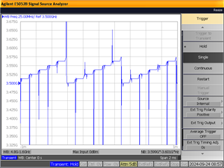
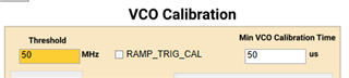
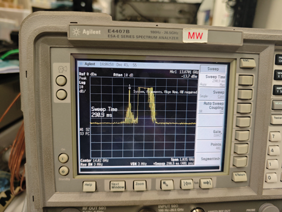
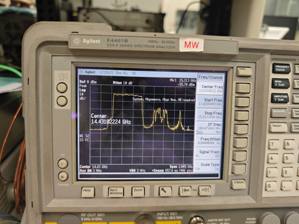
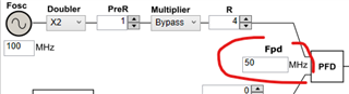
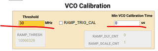
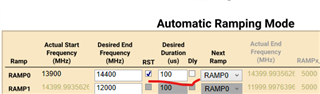
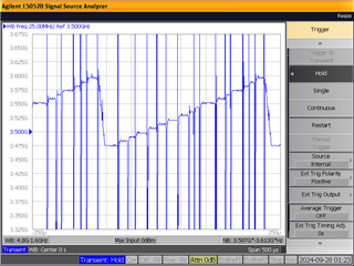
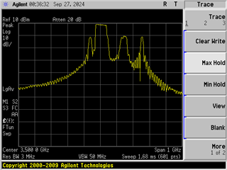
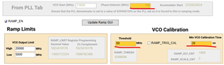
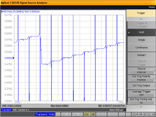
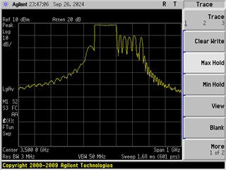
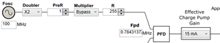
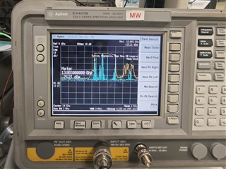
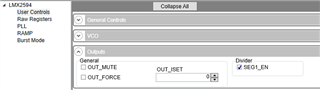
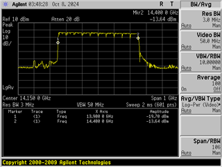
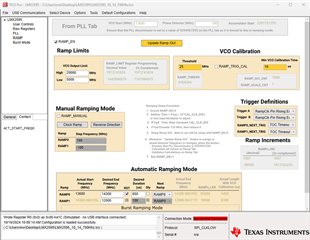
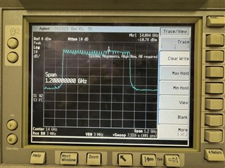
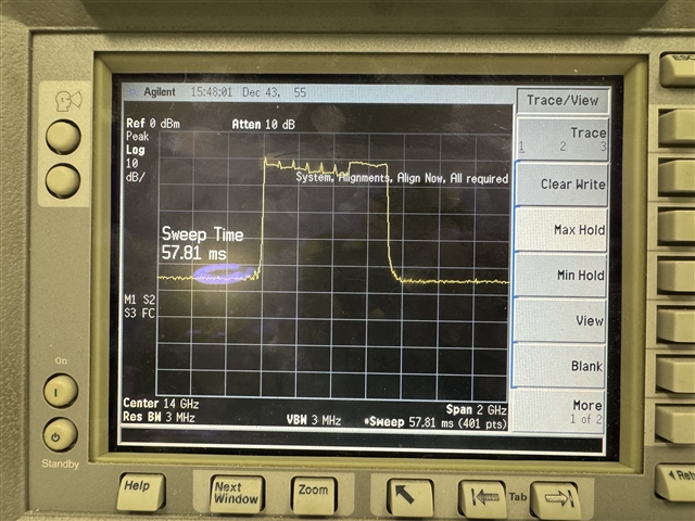
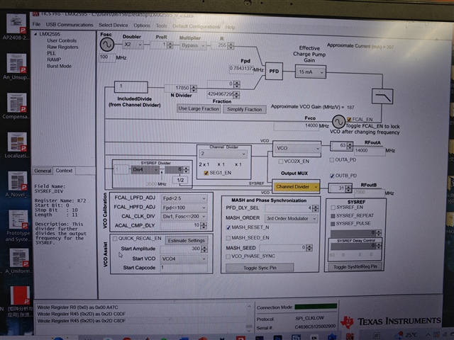
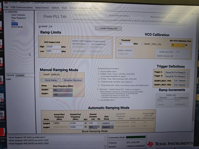
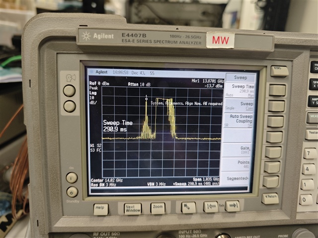
    It is found that there is a spur before a swept-frequency signal with the automatic mode of LMX2595evm. The configurations of PLL, RAMP, and the output of the spectrum analyzer are attached below. Our questions are, 

  1. how to remove the spur from the output spectrum;
  2. how to increase the output power because it now is about -3dBm and cannot meet our requirements. 

Besides, in our experiments, I don't know why the LED light D1 is unstable, and the output frequency is not the same under the same configurations. 

Best regards,

Jaffrey

  • Hi Jaffrey,

    This is due to the VCO calibration during ramp. 

    in the above plot, I have setup the threshold to 50MHz. As a result, there is a VCO calibration once the accumulated ramp frequency has reached 50MHz. VCO calibration takes place in open-loop configuration, so there are big glitches at the beginning of each calibration. 

  • Hi Noel, 

    Thank you for valuable responds. 

    I have also some questions to consult you, and they are, 

    1. How much is the maximum output power from a single port? 
    2. Why is the parameters updation of the evaluation board unstable? This means it can sometimes successfully update these configurational parameters, and sometimes it fails. Would you have some ideas to make it stable?

    Best regards,

    Jeffrey

  • Hi Jieru,

    max. possible output power depends on frequency and the pull-up component at the output.

    I don't aware we have GUI issue, do you have specific configuration example for me to try?  

  • Hi Noel, 

    Thank you for your prompt response. Attached are the configuration examples, and the center frequency of the former is from 14GHz to 14.3GHz; the center frequency of the latter is from 14GHz to 14.5GHz. However, the output spectrums, shown in the below figures, are different from the above configuration parameters. 

    LMX2595_9_23.tcsLMX2595_9_24_14Hz_14.05_5tcs.tcs

    Best regards

    Jieru

  • will check later.

  • Hi Jieru,

    There are couples of issue in the _9_24 configuration.


    Ramp duration is 100µs for 500MHz sweep range. That means the frequency change per each ramp step is more than in the _9_23 configuration, which is 300MHz in 100µs. 

    However, the loop bandwidth is reduced to approx.100kHz because fpd is only 50MHz. (assume you did not modified the loop filter). 

    Smaller loop bandwidth will take longer time for the VCO to switch frequency. Bigger frequency change will required longer switching time. These two factors added together will make the frequency change not linear because we are change VCO frequency once every fpd cycle. 

    You ask the device to calibrate once the accumulated ramp frequency reaches 30MHz but without giving it time to perform calibration. That means, there is possibility that the VCO is not settled down before ramping starts.

    As a result, you've got this uneven ramp.

    from below, you don't even get 125MHz (output is div/4 so ramp range is 500/4 = 125Mhz) sweep range.

    Suggestion: increase fpd to 100MHz, set calibration threshold to 50MHz and give it 20µs calibration time.

    the _9_23 configuration does not make sense, fpd is too low.

  • Hi Noel,

    Thanks, we will try it. 

  • Hi Noel, 

    So sorry for my late answer. I have tested my examples according to your tips, but unfortunately, the results cannot match the expectations. Attached are the tested document and the experiments' results. Would you give me some ideas that how to generate a perfect ramp signal with its bandwidth of 500MHz, its central frequency of 13.9GHz, and the swept-frequency time of less than 1 ms? Could you provide me the concrete .tcs document to me if you're convenient?
    Besides, I don't understand the relationship between the VCO calibration time, VCO calibration threshold, and phase detector frequency f_pd. According to my understanding, the whole swept-frequency bandwidth divided fpd equals some frequency segments, and the swept-frequency time of every segment can be obtained by the ramp duration time and the number of segments. The calibration time is included in the swept-frequency time of every segment. How to choose the proper VCO calibration time and VCO calibration threshold in an example.  
    Best regards

    Jieru

  • Hi Jieru,

    I suggest make fpd = 100MHz for higher loop bandwidth. 

    We can also set OUT_FORCE = 0 so that the output is muted during VCO calibration, this could make the ramp spectrum looks better.

  • Hi Nole, 

    Thank you for your suggestion, and the output frequency is much better than the previous one. 

    However, is it normal to have many ripples inner swept time when the ramp signal bandwidth is larger? Attached are the output waveform and the configurational document. If not, how can I get a good output signal?

     LMX2595_10_14_700Hhz.tcs

    Best regards,

    Jieru

  • Hi Nole 

    I just forgot to copy the output of the spectrum analyzer on the panel. 

  • Hi Jieru,

    We must calibrate the VCO after some ramp otherwise you wont' get the correct frequency. see below application note for calibration details.

    https://www.ti.com/lit/pdf/snaa336

    In your configuration, you calibrate the VCO every 25MHz. You can make it larger, say 50MHz. Larger than 50MHz and less than 100MHz should also work for most of the frequencies but issues may happen when the frequency is at the boundary of two adjacent VCO core. I recommend make it at most 50MHz.

  • Hi Noel, 

    When the frequency threshold of VCO calibration is 30MHz, the output of the spectrum analyzer is seen in the attachment. There are still many ripples in ramp duration, and the difference between the maximum of ripples and its minimum is around 6dB. 

    Would you know how to suppress these ripples, and make it flatter?

    LMX2595_10_21_700Hhz.tcs

  • Hi Jieru,

    This could be a measurement setup issue, set the sweep time smaller may help give you a better picture.

    Suggest use test equipment that can do freq vs time measurement, such modulation domain analyzer or signal source analyzer.