Part Number: LMK04906
Tool/software:
Dear team,
Now we use the LMK04906 for our design and we configured our device use the following register value.
R0 (INIT) 0x80160200
R0 0x00140300
R1 0x00140301
R2 0x00140302
R3 0x00143C03
R4 0x00140784
R5 0x80140C85
R6 0x01140006
R7 0x08110007
R8 0x04080008
R9 0x55555549
R10 0x9102412A
R11 0x0401100B
R12 0x1B0C006C
R13 0x3B02848D
R14 0x0240000E
R15 0x8000800F
R16 0xC1550410
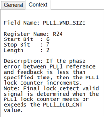
R24 0x000000D8
R25 0x02C9C419
R26 0x8FA8001A
R27 0x1900005B
R28 0x0020011C
R29 0x0180031D
R30 0x0200031E
R31 0x001F001F
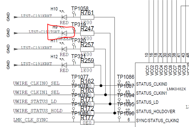
I think for the PLL1 and PLL2 have been locked after the above configuration. According to my schematic below, the H9 must be on. While now, the H9 is still off.
Could you please help us to double check on your evaluation board?
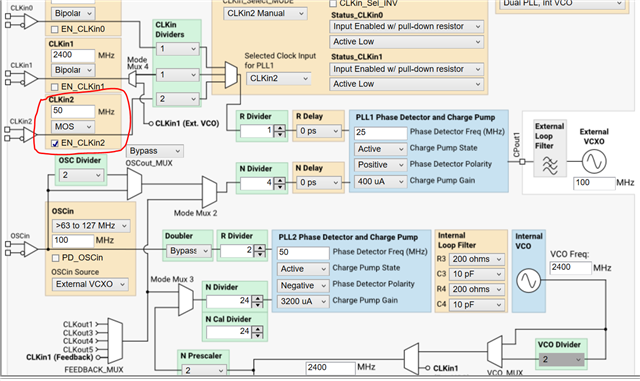
We use the CLKin2 for the reference with 50MHz sinewave which is coming from the keysight signal generator - N5182B with output power 5dBm.
External VCXO is VX-501-0208-100M0.