This thread has been locked.

If you have a related question, please click the "Ask a related question" button in the top right corner. The newly created question will be automatically linked to this question.

LMX2820: LMX2820: In some frequency bands, the chip may lose lock if the same parameter is configured multiple times.

Part Number: LMX2820

Tool/software:

Hi:

We are using LMX2820 to generate 13-20GHz signal,
In some frequency bands, the chip may lose lock if the same parameter( 2_b Change frequency operation as described below)is configured multiple times. 
For example, if you configure 20G continuously for 500 times (each time with an interval of 20ms),
the chip will lose lock around the 300th time; other frequencies such as 18.9G will not lose lock.

What could be the reason? Thanks!
The details of the chip are roughly as follows: 
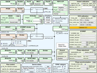
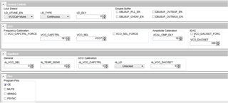
1. The chip configuration is as shown in the figure:


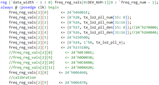
2. Register Configuration method:
a.)Initialization

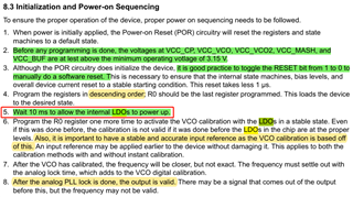
As 8.3 Initialization and Power-on Sequencing in LMX2820 datasheet.

b.)Change frequency operation


Thanks!
  • Hi Applo,

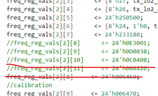
    Please try without crossed lines.

    is the problem only happen with VCO doubler frequency or only at 20GHz?

  • Hi, Noel:
    Later, we continued to try other frequencies in the 16.4-20.4GHz band.
    Some frequencies also lost lock, but the probability was different.
    I will try your suggestions later.
    I have another question.
    Are the CE PIN of LMX2820 and the POWERDOWN control bit of register R0 equivalent?
    Are they logically ANDed?

    As shown in the picture below, is it possible to do the following? 
    A.) After the LMX2820 is powered on and stabilized, pull the CE pin high;
    B.) Wait for 10ms to allow the internal LDO output to stabilize;
    C.) Program all registers in descending order, and then directly write R0 to start calibration.
    No more waiting for 10ms (the POWERDOWN control bit of R0 is always 0, and the internal LDO is always enabled).
    Thanks!


  • Hi Applo,

    Your sequence is fine, some comment below:

    A. you could also tie CE pin to Vcc (directly or via a resistor) so that when Vcc is applied, the device is power up.

    B. I suggest after the 10ms wait time, program RESET = 1 to reset the device to the known state (silicon default), then wait another 10ms. 

    C. I suggest add some delay between R1 and R0 (with FCAL_EN = 1, DBLR_CAL_EN = 1, RESET = 0, POWERDOWN = 0)

    After step C, the device should lock.