Other Parts Discussed in Thread: LMX2571
Tool/software:
Hi Expert
1.TICS PRO set up is as below, F_OSC_122.88M, F_IN_122.88M
2.Waveform of Fosc and Fin
F_IN
BRs
Peter Hsiao
Tool/software:
Hi Expert
1.TICS PRO set up is as below, F_OSC_122.88M, F_IN_122.88M
2.Waveform of Fosc and Fin
F_IN
BRs
Peter Hsiao
Hi Peter,
Did you program all registers? in the menu bar, click USB Communications --> Write All Registers.
Check to see if the SPI communication is all right. Program below register will has noticeable current change.
- Program POWERDOWN = 1
- Set TX Enable, RX Enable = 1 or 0.
Hi Noel
1.SPI communication is fine by test result as below
Program POWERDOWN=1/0 CURR= 3.02mA /5.12mA
OUTBUF_TX_EN_F1=1, OUTBUF_RX_EN_F1=1/0 CURR=5.12/4.39mA
OUTBUF_RX_EN_F1=0, OUTBUF_TX_EN_F1=1/0 CURR=5.23/4.43mA
2.Waveform of F_OSC, F_IN is as below
3.At now TP_CPout_Ext=2.2V
4.Remove F_OSC,
TP_CPout_Ext=1.98V
5.PLL LED is still not shown locked
BRs
Peter Hsiao
Hi Peter,
Is the F_osc single-ended or differential? Do you have external termination at OSCin?
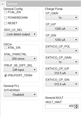
set IPBUF_SE_DEFF_SEL according to your input format. If there is no external termination, enable IPBUFDIFF_TERM bit.

Hi Noel
1."Is the F_osc single-ended or differential? Do you have external termination at OSCin?" [Peter] Yes, it is SE with a external termination.
2.After removing components of loop filter as below 1,2,3,4,5 , PLL is locked .
3.What is the current should be provided by the 5V adapter? Is it 1A enough ?
BRs
Peter Hsiao