This thread has been locked.

If you have a related question, please click the "Ask a related question" button in the top right corner. The newly created question will be automatically linked to this question.

LMX2694EPEVM: Difficulties replicating default configuration

Part Number: LMX2694EPEVM


Tool/software:

Hello,

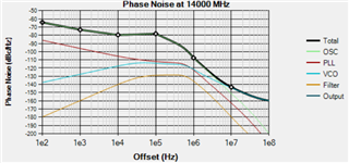
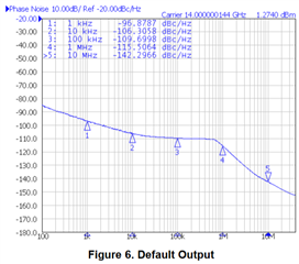
I'm struggling to recreate the default output shown in figure 6 of the LMX2694EPEVM Evaluation Instructions, also shown below:

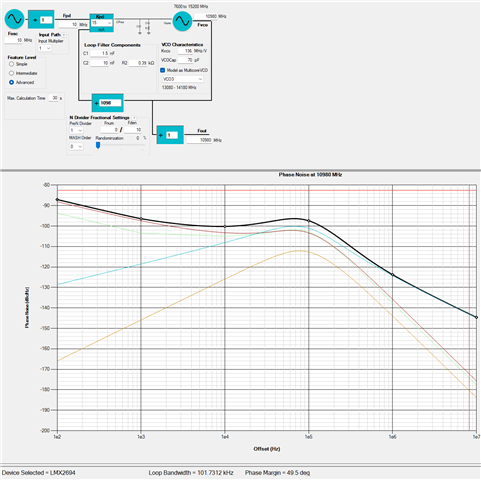
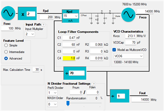
I've configured PLLatinum sim with the default loop filter that comes installed on the eval board and verified that the simulated phase noise matches what the evaluation instructions says I should be getting:

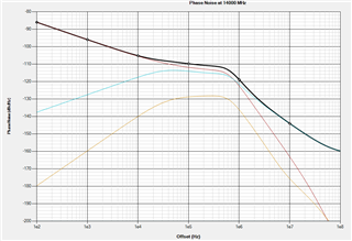
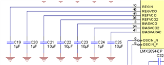
I've followed the EVM Connection Diagram shown on figure 1 of the user guide and am using a high quality signal generator at an appropriate input level to supply the necessary 100 MHz reference clock needed for this default configuration. I've verified that it shouldn't be interfering with my measurement as the phase noise of this tone is noticeably below the overall phase noise as simulated by the PLLatinum sim. It is higher at the 100Mhz range, but I'm primarily interested in the overall phase noise up to 10Mhz:

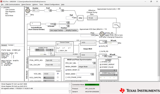
I've configured my TICS Pro instance to be identical to the PLLatinum sim but I'm getting a grossly spurious output:

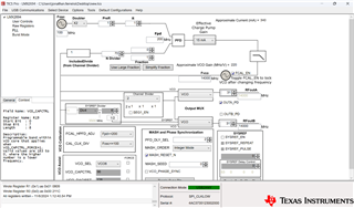
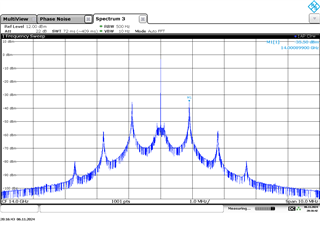
I don't think there's anything wrong with my setup (verified that the input reference is sufficiently noise free, eliminating power supply noise to eval board by using LDO, onboard LED turns green which indicates that PLL is locking) and the only thing I see potentially leading to such a degraded output signal is in how I've configured TICS Pro. Is there anything I've missed in my setup or replicating my PLLatinum Sim configuration in TICS Pro that could be leading to such a grossly degraded output signal? If not, then what else could explain such behavior?

  • Hi Johnathan, 

    Your reference clock is pretty bad. If I plug-in the reference clock noise in the simulation tool, the sim result agrees with your test data.

    As for the 900kHz spurs, looks to me they are modulation not spurs. This could be due to power supply as your reference clock does not have this modulation.

    Are you using the EVM or your own board? 

    if it is your board, verify if you have similar capacitors at the bypass pins. 

  • Hi Noel,

    I've been mulling this over and agree with you that the reference signal that I was using was genuinely very bad. I've switched to a much cleaner reference (a 10Mhz OCXO) and included that in PLLatinum sim to generate a new loop filter configuration for the LMX2694EPEVM evaluation board that I'm using. I didn't notice that I could account for the reference clock noise in the tool, but now that I'm doing so it doesn't look like it would affect my measurement like my old reference was. 

    Despite that, I'm still seeing a much worse phase noise than what PLLatinum simulates (roughly 12 to 18 dBc/hz worse across almost the entire frequency range).

    The loop bandwidth and overall shape of the total phase noise appear to be spot-on so I was wondering what else could be causing this phase noise degradation now that I've resolved my input signal?

    Thank you,

    Jonathan

  • Hi Jonathan,

    Is the 10MHz clock sine wave?

    PLL noise (not VCO noise) is very sensitive to the slew rate of the input clock, if your 10MHz clock is sine wave, this will hurt PLL noise badly.