LMX2595: LMX2595 Phase adjust and Manual RAMP

Part Number: LMX2595

Tool/software:

Hello:

At present, we are using two-channel lmx2595 for phase adjustment and manual RAMP application. I hope you can help me to answer the following questions:

Phase regulation:

11According to the calculation formula in manual 7.3.12, the calculated result is not consistent with the actual output result, and the actual adjustment Angle is much smaller than the value set by me. But when I set it to 90 degrees, the actual Angle is about the same, and I want to know what's the problem


2I noticed in 7.3.12 that the value of MASH_SEED is less than PLL_DEN, but in my actual test, values greater than PLL_DEN also have phase changes. Is there any effect when MASH_SEED is greater than PLL_DEN?


3, when using the phase adjustment function is PLL_DEN is there any restrictions? When I set PLL_DEN to 1000000000, I found that no matter how I set the MASH_SEED output phase, it didn't change.


  1. In practice, I hope that when SYNC=0, I can modify the phase difference of MASH_SEED two ways 2595 to be absolute value instead of adding some Angle to the current one.

TIP: The FOSC I use is 10M, and when both 2595s output 200M for phase adjustment, PLL_DEN is set to 2083333


Manual RAMP:

When I use the manual RAMP mode, the RAMP waveform is not stable, but when I exit the RAMP mode quickly and re-enter the RAMP waveform can be normal, and then restart the RAMP modulation can be normal output. It seems that 2592 could not parse my drive waveform correctly at the beginning, please help me analyze what caused it

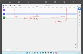
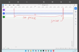
This is where I drive the waveform CLK at a frequency of 27.5KHZ and DIR pulls up every 138th pulse

This is the waveform that starts modulating after power-on

This is a normal modulated waveform


Here are my chip setup parameters:

LMX2595_R112

,

0x0000

LMX2595_R111

,

0x0000

LMX2595_R110

,

0x0000

LMX2595_R109

,

0x0000

LMX2595_R108

,

0x0000

LMX2595_R107

,

0x0000

LMX2595_R106

,

0x0000

LMX2595_R105

,

0x0021

LMX2595_R104

,

0x0000

LMX2595_R103

,

0x0000

LMX2595_R102

,

0x3F00

LMX2595_R101

,

0x0011

LMX2595_R100

,

0x0000

LMX2595_R99

,

0x0000

LMX2595_R98

,

0x0400

LMX2595_R97

,

0x0888

LMX2595_R96

,

0x0000

LMX2595_R95

,

0x0000

LMX2595_R94

,

0x0000

LMX2595_R93

,

0x0000

LMX2595_R92

,

0x0000

LMX2595_R91

,

0x0000

LMX2595_R90

,

0x0000

LMX2595_R89

,

0x0000

LMX2595_R88

,

0x0000

LMX2595_R87

,

0x0000

LMX2595_R86

,

0x9999

LMX2595_R85

,

0x9C19

LMX2595_R84

,

0x0001

LMX2595_R83

,

0x0000

LMX2595_R82

,

0x6400

LMX2595_R81

,

0x0000

LMX2595_R80

,

0x0000

LMX2595_R79

,

0x0080

LMX2595_R78

,

0x0101

LMX2595_R77

,

0x0000

LMX2595_R76

,

0x000C

LMX2595_R75

,

0x0800

LMX2595_R74

,

0x0000

LMX2595_R73

,

0x0FFF

LMX2595_R72

,

0x0000

LMX2595_R71

,

0x0001

LMX2595_R70

,

0xC350

LMX2595_R69

,

0x0000

LMX2595_R68

,

0x03E8

LMX2595_R67

,

0x0000

LMX2595_R66

,

0x01F4

LMX2595_R65

,

0x0000

LMX2595_R64

,

0x1388

LMX2595_R63

,

0x0000

LMX2595_R62

,

0x0322

LMX2595_R61

,

0x00A8

LMX2595_R60

,

0x0000

LMX2595_R59

,

0x0001

LMX2595_R58

,

0x1001

LMX2595_R57

,

0x0020

LMX2595_R56

,

0x0000

LMX2595_R55

,

0x0000

LMX2595_R54

,

0x0000

LMX2595_R53

,

0x0000

LMX2595_R52

,

0x0820

LMX2595_R51

,

0x0080

LMX2595_R50

,

0x0000

LMX2595_R49

,

0x4180

LMX2595_R48

,

0x0300

LMX2595_R47

,

0x0300

LMX2595_R46

,

0x07FD

LMX2595_R45

,

0xC8DF

LMX2595_R44

,

0x1FA3

LMX2595_R43

,

0x0000

LMX2595_R42

,

0x0000

LMX2595_R41

,

0x0000

LMX2595_R40

,

0x0000

LMX2595_R39

,

0xE100

LMX2595_R38

,

0x05F5

LMX2595_R37

,

0x8304

LMX2595_R36

,

0x03E8

LMX2595_R35

,

0x0004

LMX2595_R34

,

0x0000

LMX2595_R33

,

0x1E21

LMX2595_R32

,

0x0393

LMX2595_R31

,

0x03EC

LMX2595_R30

,

0x318C

LMX2595_R29

,

0x318C

LMX2595_R28

,

0x0488

LMX2595_R27

,

0x0002

LMX2595_R26

,

0x0DB0

LMX2595_R25

,

0x0C2B

LMX2595_R24

,

0x071A

LMX2595_R23

,

0x007C

LMX2595_R22

,

0x0001

LMX2595_R21

,

0x0401

LMX2595_R20

,

0xE048

LMX2595_R19

,

0x27B7

LMX2595_R18

,

0x0064

LMX2595_R17

,

0x0064

LMX2595_R16

,

0x0080

LMX2595_R15

,

0x064F

LMX2595_R14

,

0x1E70

LMX2595_R13

,

0x4000

LMX2595_R12

,

0x5001

LMX2595_R11

,

0x0018

LMX2595_R10

,

0x10D8

LMX2595_R9

,

0x0604

LMX2595_R8

,

0x2000

LMX2595_R7

,

0x40B2

LMX2595_R6

,

0xC802

LMX2595_R5

,

0x00C8

LMX2595_R4

,

0x0A43

LMX2595_R3

,

0x0642

LMX2595_R2

,

0x0500

LMX2595_R1

,

0x0808

LMX2595_R0

,

0x241C


你好:

目前我们在使用两路lmx2595做相位调节及手动RAMP的应用,遇到以下问题希望能帮我解答一下:

相位调节:

  • 根据手册3.12的计算公式,计算的结果与实际输出的结果并不一致,实际调节的角度要比我设置值小很多。但当我设置为90°时实际角度又差不多,我想知道是什么问题引起的
  • 我注意到3.12中说MASH_SEED的值要小于PLL_DEN ,但我实际测试时大于PLL_DEN的值也是有相位改变的 ,当MASH_SEED大于PLL_DEN时是有什么影响吗?
  • 当使用相位调节功能是PLL_DEN是有什么限制吗?当我PLL_DEN 设置为1000000000时发现无论我怎么设置MASH_SEED 输出相位都没有改变。
  • 实际使用中,我希望在SYNC=0时,当修改MASH_SEED两路2595的相位差是绝对值而不是在当前的基础上累加一定角度,这种能实现吗?

tip:我使用的FOSC10M,当两路2595都输出200M做相位调节时PLL_DEN设置为2083333


手动ramp

当我使用手动ramp模式时,ramp波形并不能稳定,但当我快速退出RAMP模式并重新进入后RAMP波形又能正常,而且之后重新开始ramp调制也能正常输出。感觉像是一开始的时候2592并不能正确的解析我的驱动波形,请帮我分析下是什么问题导致的

这是我的驱动波形 CLK的频率为27.5kHz每第138个脉冲DIR会拉高


  • Hi There,

    Instead of making a big phase change (e.g 45deg, 90deg) in one programming, I suggest make multiple small phase change.

    For example, set the phase change to 5deg, then program MASH_SEED 9 times to get 45deg phase change.

    Phase adjustment does not work with big phase change.

    PLL_DEN should not be very big, otherwise it will take very very long time for the device to respond. 

    Phase adjustment is accumulative, but not an absolute value.

    I don't understand the ramp question. Is the abnormal ramp only happened once? Only happen the first time you enable ramp after Vcc power and programming? 

  • hello
    Do I need to do a delay for continuous phase writing? What is the minimum time required? When writing a small Angle, I found that the Angle I actually appeared was much smaller than the Angle I set. For example, I set a phase of 10°, but the time felt only changed by two or three degrees. My test method is that both 2595 channels output the same frequency, record the original phase difference and then test the difference after writing down the phase.

    After the ramp mode is powered on, incorrect waveforms will always appear. When exiting and re-entering the waveform, there is a small probability that it will become normal until I exit ramp quickly and restart it (within 1s). Once the waveform is normal, the waveforms of starting and exiting RAMP mode will be normal. When I enter the RAMP mode, I will write PLL_NUM ,PLL_DEN ,RAMP0, RAMP1 and R0 to 0xA41C
    Exiting RAMP will write all registers related to the setting frequency, and R0 will write 0x241C

    The following is my test process: Power-on -> RAMP -> Error waveform -> Exit RAMP -> RAMP -> Error waveform ->.... -> Error waveform -> Exit RAMP -> 1S Enter RAMP -> Normal waveform -> Exit RAMP -> Enter RAMP -> Normal waveform....

  • Hi there,

    something like this? or can you try below sequence?

    Power on --> program all register to lock to the start ramp frequency --> program RAMP_EN = 1 --> provide 138 RampClk clocks to ramp up --> program RAMP_EN = 0 --> wait?--> program RAMP_EN = 1 --> provide 139 RampClk clocks to ramp up --> ........

  • Yes, it is currently driven in this way. Power on -> Set center frequency ->69 ramp up ->1 ramp down ->138 ramp up ->1 ramp down ->138 ramp up.... At 10GHz, if I give 138 ramp up waveforms first, it is normal, but if I change to 9.999MHz, it is still wrong to give 138 ramp up waveforms first. Also, when SYNC is equal to 1, when I CHDIV>2, can I not make the phase difference of the two ways 2595 any value from 0.00 to 360.00?

  • Hi There,

    I tried 9.9999GHz with Div/4, I am able to do manual or automatic ramp every time after doing a Vcc power up and programming. 

    When SYNC = 1, there are two issues.

    IncludedDivide maybe greater than 1. In this case, you may need to reduce fpd in order to meet min. N divider requirement. This is fine as long as you adjust CAL_CLK_DIV accordingly so that the state machine clock is equal to or less than fpd.

    Another issue, this could be the main reason of failure. If the ramp range requires a VCO calibration, then ramping will not work properly. Ramping will work in general but at some point, it will stop ramping. If we continue to toggle RampClk, at some point, it will continue to ramp. 

  • I checked MUXoutPin that the locking situation was the same in both cases,the driving waveform is the same, what else can affect ramp?

    and my app does not modulate RAMP with SYNC = 1.


    The top of the video is the MUXout Pin and the bottom is the RAMP modulation waveform

    Will RAMP improve if I use Full assist ?

  • Hi there,

    To debug, suggest you do the ramp manually or ramp at a very slow speed. 

  • Are there any other limitations to the RAMP_LIMIT_LOW and RAMP_LIMIT_HIGH Settings? When my center frequency is set to 10G and the maximum RAMP bit is 10000.1mhz and the minimum RAMP bit is 9999.9mhz, there is no waveform output in RAMP when RAMP_LIMIT_LOW = 9999.9 RAMP_LIMIT_HIGH = 10000.1

  • Hi There,

    They should be set to beyond your ramp range.

    For example, you can set them to 5GHz (LOW) and 20GHz (HIGH).

  • HI 

    Can I set it to 15G-7.5G? The 20G~10M I set with TICSPRO at the beginning can be written normally, but now TICSPRO limits me to set only 12560M~7440M. My FPD is 10M. If the center frequency is programmable (10M~20G),and the maximum range of my RAMP is ±20MHz, what range should I set?

    By the way, what effect does MASH_ORDER have on my output? I found no instructions for the MASH_ORDER setup in the manual

  • Hi There,

    When fpd is just 10MHz, this limits the possible High/Low limits. This in turn restricted your possible VCO ramp frequency range to > 7440MHz and < 12.56GHz.

    For example, if your Fout = 100MHz, ramp range is 20MHz. That means VCO ramp range is 9600MHz to 11.52GHz. 

    Almost all fractional PLL use sigma delta modulator, there are 1st, 2nd, 3rd and 4th order modulator. In general, the higher the order, the best fractional spurs performance. MASH order = modulator order.

  • hello
    Can you help me see what is wrong with the configuration of my TICS pro? When I RESET the reset bit, the first manual RAMP waveform must be wrong. I do not know where the configuration is incorrect.

     Driving wave.csv

    This is my driving wave

    RAMP_MANUAL.rar

    This is my TICS Pro engineering file

  • Hi there,

    I don't know why, I will try.

    What is the start and stop frequency?

    What is the RampClk frequency?

    How did you return the end frequency to the start frequency?

  • HI

    the start frequency is 9999M and the stop frequency is 10001M

    the RampClk frequency you can see the  Driving wave.csv,It's about 80K

    I return to the starting frequency by pulling DIR up and giving a pulse

    the D0 is DIR and the D1 is CLK

    the RAMP0_INE  set to 0.01Mand RAMP1_INE set to 1M

    max set to 0.05M and 5M

  • Hello,

    The team is out for the holidays. Please expect a response by Jan 2 at the earliest.

    Thanks,

    Kadeem

  • hello,
    Is there any progress?

  • Hi There,

    Looks like this issue is related to the state machine clock frequency.

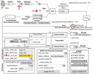
    Can you try set CAL_CLK_DIV = 0x1 and PLL_R_PRE = 2. With this configuration, both state machine clock frequency and fpd will be 50MHz.

  • hello

    I tried it as you suggested, and it didn't improve.

  • Hi There,

    Then I don't know what was happening because I cannot replicate the problem.