This thread has been locked.

If you have a related question, please click the "Ask a related question" button in the top right corner. The newly created question will be automatically linked to this question.

LMX2592: Clock output not working without power cycle

Part Number: LMX2592

Tool/software:

Hello,


We are using an LMX2592 chip in our project, and we want to be able to set every frequency (with ~1 Hz accuracy) between 100 MHz and 2.5 GHz. We have written our own driver in Python based on a C++ implementation which we found on Github (not tested), information in the datasheet and information from TICS Pro. After power cycling our board, it seems that everything is working accordingly and we can for one time set every frequency which we desire. However, if we don't power cycle the board (e.g. if we reboot it, we restart the application, or we just try to set a new frequency at runtime), we can only get a valid output with a small number of frequencies, and with most frequencies we get no output at all. Every time we start our application, we follow this startup procedure:

1. We soft reset the chip by writing first 0 and then 1 to the 'RESET' field of register 0

2. We write default register values which seem to work for us in descending order:

(First value is the address, second value is the value)
64: 0x0077
62: 0x0000
61: 0x0001
59: 0x0000
48: 0x03FC
47: 0x08CF
46: 0x0FE3
45: 0x0000
44: 0x0000
43: 0x0000
42: 0x0000
41: 0x03E8
40: 0x0000
39: 0x8204
38: 0x0036
37: 0x4000
36: 0x0011
35: 0x021F
34: 0xC3EA
33: 0x2A0A
32: 0x210A
31: 0x0601
30: 0x0034
29: 0x0084
28: 0x2924
25: 0x0000
24: 0x0509
23: 0x8842
22: 0x2300
20: 0x012C
19: 0x0965
14: 0x018C
13: 0x4000
12: 0x7001
11: 0x0018
10: 0x10D8
9: 0x0302
8: 0x1084
7: 0x28B2
4: 0x3F43
2: 0x0500
1: 0x0808
0: 0x221C

3. We read back all registers

4. We write first 0 and then 1 to the 'FCAL_EN' field of register 0

5. We read back all registers again

If we want to change the output frequency, we first determine all the required values, then we write all of the registers (only the ones which have changed) with the new values in descending order and then we run the calibration sequence again. The following values may change when changing the output frequency:

- OSC_2X
- PLL_R_PRE
- MULT
- PLL_R
- PLL_N_PRE
- PLL_N
- PLL_NUM_LSB
- PLL_NUM_MSB
- PLL_DEN_LSB
- PLL_DEN_MSB
- CHDIV_SEG1_EN
- CHDIV_SEG2_EN
- CHDIV_SEG3_EN
- CHDIV_SEG2
- CHDIV_SEG3
- CHDIV_SEG_SEL
- CHDIV_DIST_PD
- CHDIV_SEG1
- FCAL_LPFD_ADJ
- FCAL_HPFD_ADJ
- PFD_CTL
If we want to change the output power, we first determine all the required values and then we write all of the registers (only the ones which have changed) with the new values in descending order. The following values may change when changing the output power:
- CHDIV_DIST_PD
- CHDIV_DISTA_EN
- VCO_DISTA_PD
- CHDIV_DISTA_EN
- VCO_DISTA_PD
- OUTA_PD
- OUTA_POW
- CHDIV_DISTB_EN
- VCO_DISTB_PD
- OUTB_PD
- OUTB_POW
After following the startup procedure, we first set the output frequency for both ports to some value (e.g. 200 MHz) and the output power of both ports to 15. If we start with 200 MHz after a power cycle, we can write 200 MHz again and also some other values (e.g. 150 Mhz), but we cannot for example write 201 MHz. If we start with 201 MHz after a power cycle, we can write 201 MHz again and some other values, but we cannot write for example 200 MHz. We also tried to soft reset every time before writing the new frequency, but this does not help. We want to be able to all frequencies whenever we want, independent of if the chip has just power cycled and independent of which frequency it starts with after power cycle. How can we achieve this?


Thank you and we are looking forward to your response.

Kind regards,
Roy
  • Hi Roy,

    Since you have experience with TICS Pro, it would be great if you can provide your configuration in TICS Pro format.

  • Hello Noel,

    We are not using TICS Pro, we only used it once for getting default settings of the registers.

    Kind regards,
    Roy

  • Hello Noel,

    I tried to explain everything by providing the register values in the TICS Pro exported hex register values. I hope this is clear.

    Fosc = 625 MHz


    During the initial startup of the application, we first write this to reset the chip:

    R0      0x00221E


    Next, we write all initial values:

    R64     0x400077
    R62     0x3E0000
    R61     0x3D0001
    R59     0x3B0000
    R48     0x3003FC
    R47     0x2F08CF
    R46     0x2E0FE3
    R45     0x2D0000
    R44     0x2C0000
    R43     0x2B0000
    R42     0x2A0000
    R41     0x2903E8
    R40     0x280000
    R39     0x278204
    R38     0x260036
    R37     0x254000
    R36     0x240011
    R35     0x23021F
    R34     0x22C3EA
    R33     0x212A0A
    R32     0x20210A
    R31     0x1F0601
    R30     0x1E0034
    R29     0x1D0084
    R28     0x1C2924
    R25     0x190000
    R24     0x180509
    R23     0x178842
    R22     0x162300
    R20     0x14012C
    R19     0x130965
    R14     0x0E018C
    R13     0x0D4000
    R12     0x0C7001
    R11     0x0B0018
    R10     0x0A10D8
    R9      0x090302
    R8      0x081084
    R7      0x0728B2
    R4      0x043F43
    R2      0x020500
    R1      0x010808
    R0      0x00221C

    Afterwards, we first write this for calibration:

    R0      0x000000

    and then this:

    R0      0x000008


    Next, the desired clock frequency (200 MHz) and output power values (15 on both ports) are set by writing this:

    R47     0x2F00CF
    R46     0x2E0F23
    R45     0x2D2815
    R44     0x2C007F
    R41     0x29EA15
    R40     0x280C6A
    R38     0x26002E
    R36     0x240C20
    R35     0x23109F
    R12     0x0C7009
    R11     0x0B0028
    R10     0x0A11D8
    R0      0x000088


    And then we calibrate again by first writing this:

    R0      0x000080

    Followed by this:

    R0      0x000088

    Now the startup sequence is done and the output clock is 200 MHz.


    We ant to change the clock frequency to for example 201 MHz. We do this by first calculating all values again and then writing the following register values:

    R45     0x2D5E15
    R44     0x2C01ED

    And then this for calibration:

    R0      0x000080

    Followed by this:

    R0      0x000088


    This results in no more output on the clock.

    Now we want to change the frequency back to 200 Mhz. We first write this:

    R45     0x2D2815
    R44     0x2C007F


    And then this for calibration:

    R0      0x000080

    Followed by this:

    R0      0x000088


    This results in an output clock of 200 Mhz. Sometimes this also results in no output clock.


    Now we want to change the frequency back to 110 Mhz. We first write this:
    R45     0x2DB340
    R44     0x2C09D5
    R38     0x260042
    R36     0x240C42
    R35     0x23119B

    And then this for calibration:

    R0      0x000080

    Followed by this:

    R0      0x000088

    This results in an output clock of 110 MHz. Sometimes this also results in no output clock.


    The question is, why are 200 MHz and 110 MHz working (most of the times) but 201 MHz not? If we power cycle the board and we program 201 MHz from the beginning, then 201 MHz is working but we cannot set 200 MHz anymore. Why is this the case and howe can we solve it?

  • Hi Roy,

    When I use your initial register values wtih Fosc = 625MHz in TICS Pro, I've got errors. would you please check your register settings again?

  • Hi Noel,
    Thank you, we made some changes to the initial register values and to the frequency calibration procedure an it is working now more often (but still not every time). This is our new initialization procedure:

    First we reset the chip by writing this:

    R0      0x000292
    

    Then we write these initial values:

    R64     0x400077
    R62     0x3E0000
    R61     0x3D0001
    R59     0x3B0000
    R48     0x3003FC
    R47     0x2F08CF
    R46     0x2E0FE3
    R45     0x2D0000
    R44     0x2C0000
    R43     0x2B0000
    R42     0x2A0000
    R41     0x2903E8
    R40     0x280000
    R39     0x278204
    R38     0x260036
    R37     0x254000
    R36     0x240011
    R35     0x23021F
    R34     0x22C3EA
    R33     0x212A0A
    R32     0x20210A
    R31     0x1F0601
    R30     0x1E0034
    R29     0x1D0084
    R28     0x1C2924
    R25     0x190000
    R24     0x180509
    R23     0x178842
    R22     0x162300
    R20     0x14012C
    R19     0x130965
    R14     0x0E018D
    R13     0x0D4000
    R12     0x0C7009
    R11     0x0B0028
    R10     0x0A11D8
    R9      0x090302
    R8      0x081084
    R7      0x0728B2
    R4      0x041943
    R2      0x020500
    R1      0x01080B
    R0      0x000290


    Next, we program the chip to generate an output of 200 MHz:

    R47     0x2F00CF
    R46     0x2E0F23
    R45     0x2D2815
    R44     0x2C007F
    R41     0x29EA15
    R40     0x280C6A
    R38     0x26002E
    R36     0x240C20
    R35     0x23109F


    Then we enable frequency calibration:

    R0      0x000298

    Then wait for 1 second and then we disable frequency calibration:

    R0      0x000290


    If we want to change the frequency to something else, we first write the changed register values and then we calibrate as described above. It seems to work for most frequencies. However, if we change it to specifically 110 MHz, the output frequency becomes ~87 MHz. This is how we write 110 MHz:
    First we write these registers:

    R45     0x2DB340
    R44     0x2C09D5
    R38     0x260042
    R36     0x240C42
    R35     0x23119B

    Then we calibrate by first writing this to enable calibration:

    R0      0x000298

    And then wait for 1 second and then write this to disable calibration:

    R0      0x000290

    We tried to increase the time between enabling and disabling frequency calibration from 1 second to 10 seconds, but this does not help. If we import the register values in TICS Pro, it seems the output frequency is correct, but when we measure it with an oscilloscope, it is not correct. Do you have an idea what might be the problem?

  • Hi Roy,

    First of all, do not use CP_ICOARSE, otherwise the lock detect may not work properly, see the recommendation in the latest version datasheet.

    this is your current configuration:

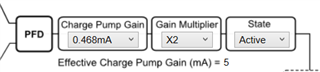
    change it to below result in the same charge pump current without enabling CP_ICOARSE.

    Secondly, R0 bit 13 should be set to =1 to enable lock detect, unless you don't use it.

    Your initialization and 200MHz clock generation can, indeed, combine in one single sequence. Program R64 to R0 (FCAL_EN = 0), wait for 10ms, then program R0(FCAL_EN=1). You can keep FCAL_EN = 1 all the time. The 10ms wait time applies to initialization only.

    For 110Mhz output, your VCO is over 7GHz, this is an invalid configuration.

    To get 110Mhz, VCO should be in the range of 3564MHz to 3996MHz, see latest version datasheet for details.