This thread has been locked.

If you have a related question, please click the "Ask a related question" button in the top right corner. The newly created question will be automatically linked to this question.

LMX2595: Failure at Power On

Part Number: LMX2595

Tool/software:

Hi There,

I have question about fatal failure that I'm seeing hoping someone can help. I have >20 of these parts with different date code and used on 6 different unit. So far more 8 of them failed and at least one time for each unit. It seem like most of the failure at power On. Some part continue to work after replace with new one and some just fail after some number of power cycle. A single power supply was use with soft start startup look without any sharp rise edge, see capture below.

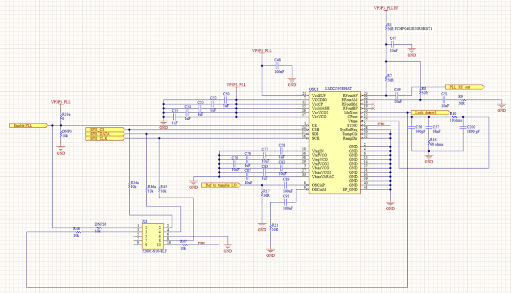
All of the lump components use in the design are the same value as it was in the evaluation board, except for the pull-up resistor on CE (Pin1) line and the biasing cap on VbiasVCO2 (Pin27). Please see below.

I'm not sure if the 0ohm pull-up resistor will cause the PLL to fail but hoping someone can confirm and if they are seeing similar issue before.

Eval Board:

CE (Pin1) = 100k pull-up resistor

VbiasVCO2 (Pin27) --> 10uF, but datasheet said to use 1uF.

Design:

CE (Pin1) = 0k pull-up resistor

VbiasVCO2 (Pin27) --> 1uF

Thank you

Eval Board

Schematic
Power Supply
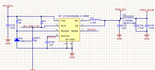
  • Nam,

    As a general practice, it is good toggle the RESET bit as described in section 7.5.1 in the datasheet.

    Also, after the device is reset, you then program the registers and then wait 10 ms and then program register R0.

    When register R0 is programmed, the VCO calibration is activated.  As we have many internal LDOs, we say wait 10 ms to be sure that all the LDOs and bias levels are proper when the calibration is run so the device will lock properly.  If these voltages are off, it can cause the VCO to miscalibrate and it will not recover if the voltage returns to its proper state.

    Regards,

    Dean

  • Hi Dean,

    Thank you for prompt respond. We double checked the program and RESET on that section before posting the thread and it look like we are following the datasheet recommended. We have used this part on other design and work fine.

    Can you help confirm if it is ok to use 0ohm pull-up on CE pin. Will this cause any current draw issue that can potentially damage the part?

    Thank you,

    Nam

  • Hi Dean,

    I also notice that the program is not happy with the "FCAL_HPFD_ADJ" valued we have selected in the capture below. Can this also cause calibration issue?

    Thank you,

  • Hi Nam,

    fpd = 100MHz, so FCAL_HPFD_ADJ should be 0x0 (Fpd <= 100).

    Tie CE pin directly to Vcc is not an issue. However, according to your schematic, you are never able to make CE pin LOW because this pin is tied to Vcc via a 0Ω resistor. 

    Another issue in the schematic is R1, it could be a ferrite bead but not a 50Ω resistor. We should also add a high-frequency decoupling capacitor next to R7 and R8.

    What does "failure" mean? The device is not locking, working or anything else?

  • Hi Noel,

    Thank you for the input. The "failure" mean that the device not respond at all. No RF output and cannot reprogram etc... We not sure if it is complete damage or not. 

    Also, we just have new testing data shows that our power supply have about 600mV of residue voltage (due to capacitor) on the supply even after the device turned off. Can this potentially cause issue to the LMX2595 power up cycle sequence?

    Does the LMX2595 have internal power-on-reset circuitry that somehow confused it power sequence due to this residue voltage?

    I noticed Dean mentioned the LMX2595 have internal LDO and I'm curious if LMX2595 require specific initial voltage at power on. In other word, can the LMX2595 have starting voltage said, 0.6V or 1.2V before transition to the 3.3V?

    Thank you,

  • Or does the LMX2595 startup voltage is required to be at 0V?

    Thank you,

  • Hi Nam,

    We don't know if the 0.6V residual voltage will be causing problem, we always start up the device from 0V. 

    The device has internal POR, after a Vcc power up, the POR will reset the device to a known state and clear all the registers to their silicon default values. To play safe, we recommend program RESET=1 after POR to also reset the device to a known state. 

    After POR and resetting the device, to debug, program POWERDOWN = 1, if you see a reasonable current change, that means the device is under control. Complete the programming using below configuration, the circled parameters are the recommended values for no assist VCO calibration.