This thread has been locked.

If you have a related question, please click the "Ask a related question" button in the top right corner. The newly created question will be automatically linked to this question.

LMK5B12204: Loss of lock DPLL

Part Number: LMK5B12204
Other Parts Discussed in Thread: AM6411

Tool/software:

Hello,

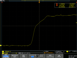
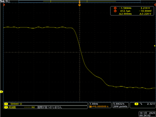
I am trying to output a 27MHz clock from lmk5b12204 PLL2, but the read value of R14 Register is 0xD0 and the DPLL is not locked.

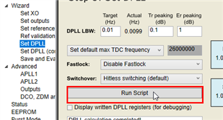
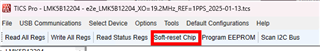
I am loading the attached tcs file with TICS Pro and writing the registers of lmk5b12204 via I2C.

I would like to find out why the DPLL does not lock. Could you please check if there are any problems with the TICS Pro settings or the register write values ​​of lmk5b12204?

For reference, when the DPLL is not locked, R13 = 0x00, R14 = 0xD0, R167 = 0x00, and R411 = 0x00.

PPS is output from the CPU.

CPU:AM6411

Clock Synthesizer: lmk5b12204

xo :19.2MHz 0.5ppm

Thank you,
Tanaka

test5_1PPS_default_modify.tcs

  • Hi Tanaka,

    What version of TICS Pro are you using? It looks like the reference is not being validated based on the R411 value.

    Can you please share an oscilloscope shot of the 1PPS input? Is the input a 50% duty cycle signal?

    Let me get back to you next week after testing your config.

    Regards,

    Jennifer

  • Hello Jennifer,

    The version of TICS Pro is v1.7.7.5.

    The PPS duty cycle is set to 50%.

    I have attached a PPS waveform image confirmed with an oscilloscope.

    ・Rising edge

    ・Falling edge

    As additional information, when writing to the lmk5b12204 registers (R0 to R352) via I2C, using single write instead of block write made a difference.
    When I used the attached test3.tcs file and set the register write to single write, the results became R13 = 0x00, R14 = 0xC0, R167 = 0x01, and R411 = 0x04.
    However, the DPLL is still not locked.
    Therefore, I would like to ask you to check that there are no problems with the settings in the test3.tcs file.
    (Please delete test5_1PPS_default_modify.tcs.)

    test3.tcs


    Thank you,
    Tanaka

  • Hi Tanaka,

    Did you click on the Run Script button? The button is found on the DPLL page and generates the DPLL settings required. The button needs to be pressed because the XO input frequency you are using is different than the one used in Default Configuration.

    MATLAB Runtime R2015 v9 is required for the Run Script operation.

    I have clicked on the Run Script with your test3.tcs. Please try again with this file:

    test3_LMK5B12204_run_script.tcs

    Regards,

    Jennifer

  • Hello Jennifer,

    I tried clicking the Run Script button on my test3.tcs and retesting, but the DPLL did not lock.
    Even with test3_LMK5B12204_run_script.tcs, DPLL did not lock.

    Thank you,
    Tanaka

  • Hi Tanaka,

    Thank you for the update. I will check in lab this week.

    Regards,

    Jennifer

  • Tanaka,

    Please try with this configuration instead. I have tested the .tcs file in lab and confirm the DPLL locks. LOPL and LOFL status bits are 0 and the PRIREF VAL STAT bit is 1.

    e2e_LMK5B12204_XO=19.2MHz_REF=1PPS_2025-01-13.tcs

    Make sure to issue a SWRST each time after loading a new .tcs file to ensure the APLL calibration can re-initiate.

    Regards,

    Jennifer

  • Hello Jennifer,

    I tried "e2e_LMK5B12204_XO=19.2MHz_REF=1PPS_2025-01-13.tcs", but the DPLL did not lock on my custom board.
    Even when I issued SWRST, it remained unlocked.
    We are investigating the cause of the issue not locking, but we have not been able to resolve it yet.

    Is there anything else I should check?

    Thank you,
    Tanaka

  • Hi Tanaka,

    1. Is this test being done on a customer board or TI evaluation module?
    2. Is TICS Pro used to program the LMK device or is programming performed by an external device like the CPU or AM6411?
    3. With the configuration I provided, can you please reshare the status signals? R13, R14, R19, R20, R80, R167.

    Regards,

    Jennifer

    Jennifer

  • Hello Jennifer,

    1. This test was done on a custom board. I do not have a TI evaluation module.
    2. The LMK devices are programmed via I2C from the AM6411.
    3. R13=0x00, R14=0xC0, R19=0x0D, R20=0xF8, R80=0x00, R167=0x01

    Thank you,
    Tanaka

  • Hi Tanaka,

    Our team is back from a US holiday (Jan 20 2025), I will get back to you this week.

    Regards,

    Jennifer

  • Hi Tanaka,

    1. Thank you for sharing the details.
    2. I see that the PRIREF validation signal is checked (meaning the 1PPS input is considered valid by the LMK) but the DPLL LOFL (loss of frequency lock) is still 1. LOPL (loss phase lock) will not clear until LOFL clears. We need to identify what is causing LOFL to not clear.
    3. Can you please perform a readback after writing to all of the LMK registers?
      1. The idea to compare the readback with the configuration file to confirm the configuration was successfully written.
    4. Please probe the 1PPS input and one of the LMK outputs on the oscilloscope and send me a picture of what you see.
      1. The idea is to check if the scope can trigger or if the two signals are drifting.
    5. Additionally, please poll the APLL NUM STAT (R127 to R123, low to high byte) over time and send me the plot.
      1. I would like to see if the APLL NUMSTAT value is updating. This register is the APLL numerator status signal; the APLL numerator is controlled by the DPLL to perform the phase correction needed to lock with the 1PPS input. The register can let us know the behavior of the DPLL.
    6. I want to confirm that your XO input is allowing APLL1 to lock. To check this, please turn of the 1PPS input to force the device into holdover mode (outputs follow the XO input stability and frequency accuracy). Next, readback the registers (R13, R14, R19, R20, R80, R167, R357, R367) and let me know.
      1. The idea is to see if the BAW LOCK status signal (R80[7]) is set; this means APLL1 is locked to the XO input. The BAW lock is a frequency  detector that checks the ppm error between the VCO output and XO input.
  • Hello Jennifer,

    We apologize. There seems to have been a problem with the way the LMK register was written.
    The problem was solved by improving the way the register was written,
    and the DPLL now locks.

    I was writing 0x00 to free registers (R9, R31, etc.) in TICS PRO.
    By not writing anything to that register, R14 is now 0x00.

    Thank you for your cooperation in investigating and resolving the problem.

    Regards,
    Tanaka