This thread has been locked.

If you have a related question, please click the "Ask a related question" button in the top right corner. The newly created question will be automatically linked to this question.

LMX2572LP: Looking for a Chip with much lower Spurs

Part Number: LMX2572LP
Other Parts Discussed in Thread: LMX2571

Tool/software:

Hello

We use the LMX2572LP in our radio modules.

This works well up to 500 mW transmission power.

However, we would like to create a concept with 6 watt rf-power but

the spurs are to strong for that. We have to comply with -54 dBm interference

levels in the EU. What we are looking for ist a comparable chip that produces

significantly fewer Spurs.

The rf carrier at 140 MHz is here suppressed with a notch filter.

with best regards
  • Hi Dirk,

    What is your PLL configuration?

  • Hi Noel

    I can't answer your question because the development was done by an external developer. He says he can't do any more.

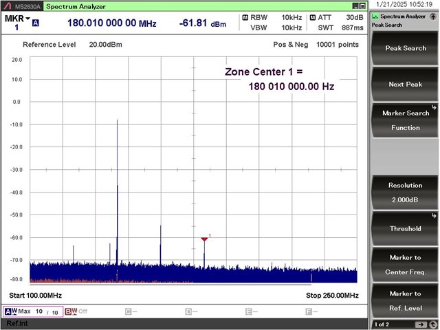
    I have here a spectrum from the beginning of the development which we made with the evaluation board.

    This seems to show us the normal spur behaviour of the chip.

    Or is there a better way and we have done something wrong?

    The spurs there are at -80 / -90 dBm. For 6 watts we have to use just under

    40 dB amplification and so -90 dBm becomes -50 dBm and that is too much for the EN300113.

    That's why we thought there might be a similar chip with better spur behaviour. What is typical for such chips?

    best regards

  • Hi Dirk,

    Looks to me that these spurs are related to the reference clock to the synthesizer. What is the reference clock frequency?

    What kind of reference clock it is? Can you share the schematic?

  • Hi Noel

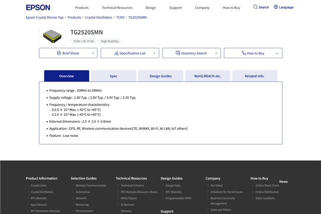
    For our rf modules we use the TG2520SMN with 50 MHz oscillator frequency. This is doubled to 100 MHz in the LMX 2572 LP.


    https://www.epsondevice.com/crystal/en/products/crystal-oscillator/tg2520smn.html


    This measures the spectrum in picture 1.

    Figure 2 is measured with the original 100 MHz oscillator of the evaluation kit.

    We have also carried out a comparative measurement between our board and the evaluation kit and could not find any major differences between the two.

    That's why the idea came up that these spurs are a fundamental problem of this technology and cannot be avoided. And we ask ourselves whether there are better and worse chips, perhaps depending on the power consumption.

    None of this would be a major problem if the limit value for interference emissions in the EU was -36 dBm for all frequencies, but unfortunately we have to comply with -54 dBm in wide frequency ranges.

    If these spurs are a fundamental technology problem, we need to find another solution for the 6 watt project.

    best regards

    D.W.

  • Hi Dirk,

    With 50MHz input and carrier = 140MHz, fractional spurs frequencies are multiple of 20MHz. 

    if you need spurs better than -90dBm for all the frequency channels, I am afraid there is no simple solution if we just play around the configuration of the synthesizer. 

  • Hi Noel,
    if we can't get the spurs down to an appropriate level with just the chip configuration, what solution would you propose instead?
  • Hi Dirk,

    I believe your application has many frequency channels, and if your specification requires spurs better than -90dBm, I think synthesizer (PLL with integrated VCO) may not be a good solution as the crosstalk within the chip is unavoidable. Like the 20MHz spurs in this case, it should be filtered out by the loop filter, but I can see they are -75dBm in the EVM. This level of spurs is not bad but still far from your target. Very likely this is due to crosstalk, something we cannot improve by external means. 

    I guess you need discrete solution, i.e. PLL + VCO, to meet the spurs requirement.

  • Hi Noel.

    Thanks for your support. The crosstalk you are talking about comes from the digital part and goes into the VCO?

    So it should be better with an external VCO?

    Do you have a PLL IC for an external VCO that has an internal VCO buffer and divider by 2 and where we can modulate by changing the N.divider?

    best regards

    D.W.

  • Hi Dirk,

    Crosstalk could happen within the chip and between the input and output; input and VCO, etc. This is because the die is small but with everything integrated, so a discrete solution could avoid crosstalk. 

    Why do you need div/2? Is your VCO 300MHz?

    LMX2571 supports external VCO and allows using the internal divider and output buffer. It also support FSK modulation, if you have a powerful processor that handle pulse-shaping and over-sampling. 

    https://www.ti.com/product/LMX2571

    https://www.ti.com/lit/pdf/sszt995

    https://www.ti.com/lit/pdf/snaa309

  • Hi Noel

    We use the frequency ranges from 140 to 174 MHz and 400 to 470 MHz. Our receiver chip is a direct mixer that wants to have twice the receive frequency as LO. The LMX 2571 looks interesting and we will take a closer look at it. Thanks for your support.

    best regards

    D.W.