


Part Number: CDCE913
Other Parts Discussed in Thread: CLOCKPRO
Tool/software:
Hi all,
we plan to use CDCE913 in a redesign to replace a discontinued part.
It is used as main clock source for a C2000 microcontroller.
The requirement is to provide any frequency between 19.0 and 20.0 MHz with 5 kHz step width, and to switch between 2 arbitrary frequencies in this range at a rate of up to 50 Hz without glitches or frequency overshoot.
PLL Clock source is a 20 MHz XTAL. The CDCE913 seems fine for this.
However, we do not know the required frequencies in advance, i.e. we have to calculate the PLL register settings "on the fly" in the microcontroller. Hence, we cannot use TI ClockPro to precalculate the register data.
With the information in the datasheet we can calculate N, P, Q, R and Pdiv register data for given Pdiv, N and M.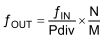
But for most frequencies there are multiple combinations of Pdiv, N, M that lead to the desired output. Which to chose?
Question 1: is there a document describing how to chose Pdiv, N, M for given fIn and fOut?
Question 2: Will all possible combinations of Pdiv, N, M work, as long as these constraints are met: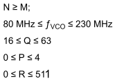
Our approach is now as follows:
Use fixed values Pdiv1 = 8 and M = 500 and vary N from 3800 to 4000 to get 19.0 to 20.0 MHz output in even 5 kHz steps.
fVCO runs at 152 to 160 MHz in 40 kHz increments.
Question 3: Will this work?
I tried TI ClockPro for some frequencies to compare the results with our approach.
ClockPro seems to try to maximize Pdiv, maybe to improve jitter performance, leading to different results than with our simple approach.


