This thread has been locked.
If you have a related question, please click the "Ask a related question" button in the top right corner. The newly created question will be automatically linked to this question.
Tool/software: TI TICS PRO 1.7.7.6
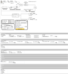
I have 2 boards each with a LMX2572LP. Both are supplied with an identical 10Mhz input clock, and both are connected to one TI Reference Pro board, and both are programmed to output 200Mhz. Both are also supplied with an identical SYNC signal, which is 0 - 3V, on time of 733us, and period of 3 seconds. I'm able to program both parts simultaneously and see the 200Mhz output signals without issue. However, the SYNC functionality doesn't seem to work properly at all. I'm able to see both generators startup and run with random phase differences by toggling the POWERDOWN and/or reset bit in register R0, as expected, but the SYNC signal will either do nothing at all, or will create what seems like 1 of about 10 phase differences between the two signals every time it occurs (in this case every 3 seconds). 1 of those phase relationships is what I'm looking for--the two signals at the same phase--but it only happens randomly and occasionally. The settings I am using are shown below.
I have played around with MASH_RST_COUNT as well as all the other registers, but nothing I've tried seems to fix the issue--I can definitely make it worse, but not better.
(All my cables and traces are very tightly length and impedance matched, so I don't think that's an issue. )
Any help would be VERY appreciated!
This is a dump of all the register settings I have now:
R125 0x7D0820 R124 0x7C0000 R123 0x7B0000 R122 0x7A0000 R121 0x790000 R120 0x780000 R119 0x770000 R118 0x760000 R117 0x750000 R116 0x740000 R115 0x730000 R114 0x727802 R113 0x710000 R112 0x700000 R111 0x6F0000 R110 0x6E0000 R109 0x6D0000 R108 0x6C0000 R107 0x6B0000 R106 0x6A0007 R105 0x694440 R104 0x6803E8 R103 0x670000 R102 0x660000 R101 0x650000 R100 0x6403E8 R99 0x63AE14 R98 0x62011C R97 0x610000 R96 0x600000 R95 0x5F0000 R94 0x5E0000 R93 0x5D0000 R92 0x5C0000 R91 0x5B0000 R90 0x5A0000 R89 0x590000 R88 0x580000 R87 0x570000 R86 0x560000 R85 0x552800 R84 0x540000 R83 0x53FFFF R82 0x52FFFF R81 0x510000 R80 0x500000 R79 0x4F0300 R78 0x4E0107 R77 0x4D0000 R76 0x4C000C R75 0x4B0940 R74 0x4A0000 R73 0x49003F R72 0x480001 R71 0x470081 R70 0x46C350 R69 0x450000 R68 0x4403E8 R67 0x430000 R66 0x4201F4 R65 0x410000 R64 0x401388 R63 0x3F0000 R62 0x3E00AF R61 0x3D00A8 R60 0x3C03E8 R59 0x3B0001 R58 0x3A1001 R57 0x390020 R56 0x380000 R55 0x370000 R54 0x360000 R53 0x350000 R52 0x340421 R51 0x330080 R50 0x320080 R49 0x314180 R48 0x3003E0 R47 0x2F0300 R46 0x2E07F0 R45 0x2DC60A R44 0x2C0A23 R43 0x2B0000 R42 0x2A0000 R41 0x290457 R40 0x280000 R39 0x270001 R38 0x260000 R37 0x258205 R36 0x2400A0 R35 0x230004 R34 0x220010 R33 0x211E01 R32 0x2005BF R31 0x1FC3E6 R30 0x1E0CA6 R29 0x1D0000 R28 0x1C0488 R27 0x1B0002 R26 0x1A0808 R25 0x190624 R24 0x18071A R23 0x17007C R22 0x160001 R21 0x150409 R20 0x144848 R19 0x1327B7 R18 0x120064 R17 0x11008A R16 0x100080 R15 0x0F060E R14 0x0E1820 R13 0x0D4000 R12 0x0C5001 R11 0x0BB018 R10 0x0A10F8 R9 0x090004 R8 0x082000 R7 0x0700B2 R6 0x06C802 R5 0x0530C8 R4 0x040A43 R3 0x030782 R2 0x020500 R1 0x010800 R0 0x00601C
Hi David,
This is a Cat.2 sync, you only need to keep VCO_PHASE_SYNC_EN = 1 all the time, then after programming, all devices will phase align.
I see in your configuration, PLL_DEN = 1 while you have enabled MASH_SEED and have a value greater than 1. This is not a valid configuration. I think MASH_SEED is making the trouble to you.
Hi Noel, Thanks for your reply!
I've tried disabling the MASH_SEED_EN, as well as setting it to 0, but this makes no difference. I have also tried setting the fractional denominator to 0, to 10000, and no change. When I pull the devices out of reset and write all registers they come up with random phases.
Hi Noel, I have been using a sine wave, but I just tried it with a 10Mhz 50% square wave and am getting exactly the same results. I also just tried it with a 5Mhz input square, both with and without the input doubler enabled, and same results. I've also tried varying the amplitude of the input clock and the only change I see is when it is too low and lock doesn't occur.
(Also, its worth mentioning that in between changes (input signal or register settings), I always reset both chips through the General Controls->Reset command, and then run the write all registers command. I can always see both outputs turn off when I issue the reset command, and then they come back up with random phases after writing all registers. I have both boards connected in parallel to one TI Ref Pro board (USB-SPI converter).
Hi David,
I think the RESET operation is causing the issue.
This is actually a TICS Pro problem, not device problem.
in TICS Pro, after programing RESET = 1. Do the following before de-assert the RESET.
- in the menu bar, click Options, then uncheck AutoUpdate
- Set RESET = 0 (this will not program the device)
- again in the menu bar, click Options, then check AutoUpdate
- Ctrl+L to program all registers
Hi Noel,
From a quick test following your procedure, this does seem to make a difference, and I'm not able to reproduce the phase jumping every time I issue a SYNC signal. But why??????
in TICS Pro, after programing RESET = 1. Do the following before de-assert the RESET. Register 00 is set to 601E
- in the menu bar, click Options, then uncheck AutoUpdate Nothing programmed
- Set RESET = 0 (this will not program the device) Nothing programmed
- again in the menu bar, click Options, then check AutoUpdate Nothing programmed
- Ctrl+L to program all registers All registers programmed, ending with reg 00 set to 601C
Versus what I was doing previously:
-Auto update on
-Set RESET = 1. Register 00 is set to 601E
-Set RESET = 0. Register 00 is set to 601C
-program all registers All registers programmed, ending with reg 00 set to 601C
-and the phase now jumps around on nearly every SYNC pulse
In all cases, the only value difference for Reg 00 is the RESET bit.
I won't say its solved just yet, since we'll have to test more (most notably using 2 separate USB_SPI converters), but this is looking hopeful. Thanks!