This thread has been locked.

If you have a related question, please click the "Ask a related question" button in the top right corner. The newly created question will be automatically linked to this question.

LMK05318B: How to configure ZDM in TICS Pro.

Part Number: LMK05318B
Other Parts Discussed in Thread: LMK5B33216, LMK5C33216A, LMK5B12204

Tool/software:

Hello,

I want the LMK05318B to output a clock synchronized to a 1PPS reference input.

I was able to configure it in TICS PRO, and the DPLL locked onto the 1PPS reference, giving me a 1PPS or 25Hz output on out7, but there is a phase offset between these outputs and the rising edge of the reference.

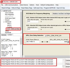
I tried to use ZDM to deal with the phase offset, but the ZDM item in TICS Pro has been deleted and can't be found.

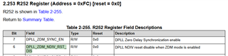
So I tried writing 1 to the DPLL_ZDM_SYNC_EN bit of R252 in the Raw registers section and checking CH7_SYNC_EN in the Outputs section, but the phase offset was not resolved.

How can I enable ZDM for LMK05318B in TICS PRO 1.7.7.6?

Regards.

Takaya

  • Hi Takaya,

    The ZDM available on the LMK05318B is not true ZDM -- it is an open loop synchronization.  So for low frequency like 1 Hz/1-PPS it is suitable; however increasing the OUT7 frequency increases the input to output phase deviation.

    More details are explained in this prior thread: https://e2e.ti.com/support/clock-timing-group/clock-and-timing/f/clock-timing-forum/1438542/lmk05318b-lmk05318b-1pps-input--output-phase-lock-time-at-zdm. LMK5B33216 family or LMK5C33216A family is preferred for true deterministic ZDM mode.

    I will correct the datasheet within the coming months to clarify the feature.

    The ZDM register was removed in TICS Pro to avoid confusion. There are plans to add the register back with a rename. A more proper term for the registers would be "SYNC_PPS_OUT7" as the function relies on syncing and does not have a deterministic phase.

    With that said, is the open-loop "ZDM" used in LMK05318B something you would like to use?

    Regards,

    Jennifer


  • Hi Jennifer,

    Thank you for answer,

    I'm planning to use the LMK05318B to generate a clock for a system that operates multiple devices in sync. Therefore, we would like to input 1PPS from GPS as a reference to each LMK05318B and obtain a clock synchronized to 1PPS from each. 

    It would have been fine if the phase offset could be kept roughly constant even if the output clocks were not perfectly synchronized, but the phase offset changed randomly with every power cycle and soft reset. Of course, if the phase difference between the 1PPS reference and output clock is random and within the range of 0 to 360 degrees depending on the lock timing of the internal PLL, it is no longer possible to talk about synchronization between devices.

    If we can reduce the phase offset variation between the 1PPS reference and the 1PPS output of Out7, we hope to be able to obtain clocks for the other outputs that are synchronized with Out7. So I was thinking of using the LMK05318B's ZDM, even if it wasn't true ZDM, as long as it could suppress the fluctuations in phase offset between input and output.

    I thought I would try it out first to see what would happen.
    However, if you professionals find it impossible or difficult to use the LMK05318B for that purpose, I will have to consider a different method.

    Regards,

    Takaya

  • Hi Takaya,

    Please try setting R252[7:6] = 0x3 to enable the "ZDM" on the LMK05318B.

    Also make sure R71[5] = 1 to enable OUT7 SYNC.

    The phase offset registers are R340 to R345.

    You may also test with the LMK5B12204 TICS Pro profile; the ZDM option has not been removed yet. The LMK5B12204 is the 4 output version of the LMK05318B. This profile should only be used to get the phase offset registers to test the "ZDM" functionality on the LMK05318B.

    If the phase deviation is still too high with this "ZDM" enabled on LMK05318B, then I suggest using the LMK5B33216 device family instead.

    Regards,

    Jennifer