This thread has been locked.

If you have a related question, please click the "Ask a related question" button in the top right corner. The newly created question will be automatically linked to this question.

Reduce Phase Noise and Fractional Spurs for LMX2541 PLL (National Semiconductor)

Other Parts Discussed in Thread: LMX2541

Hi there,

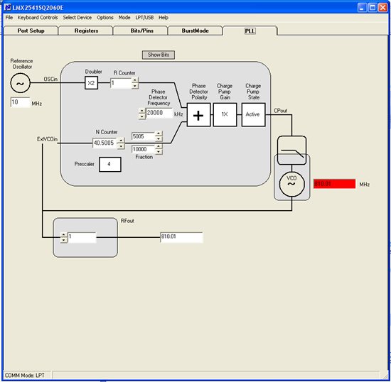
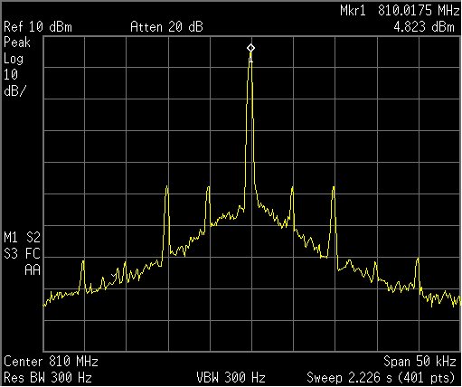
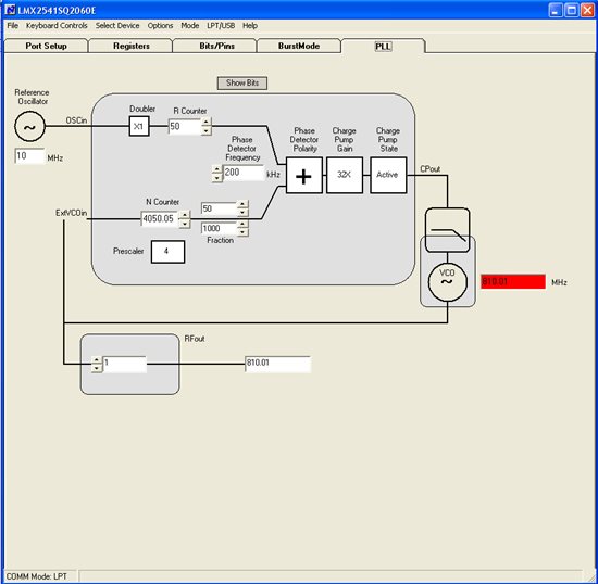
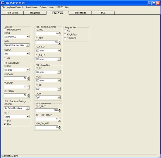
I am working on a project which uses the LMX2541 PLL+VCO chip to generate an ultra-low noise carrier frequency at 810.01 MHz. I am using an external VCO working from 805 MHz to 815 MHz and an external reference XO working at 10 MHz (The LMX2541 is working in External VCO mode.). The RFoutEN is turned off and I am extracting the 810.01 MHz signal directly from the VCO chip. The LMX2541's registers are configured as shown below.

R7 0x00000017
R13 0x0000008D
R12 0x0000001C
R9 0x28001409
R8 0x0111CE58
R6 0x001F3306
R5 0xA0000005
R4 0x00001644
R3 0x013A7F13
R2 0x04003E82
R1 0x00000321
R0 0x0032FD20


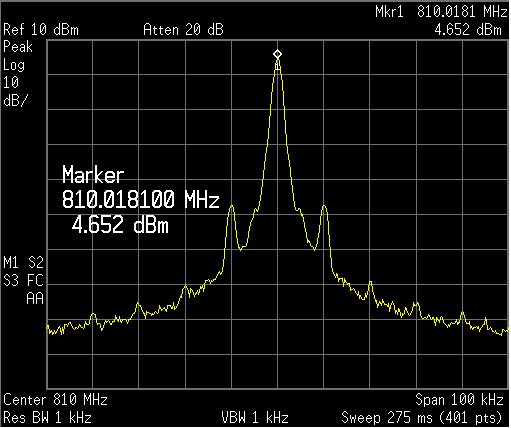
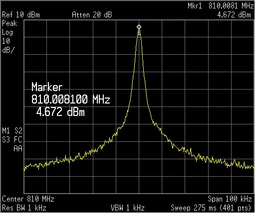
The purpose of this project is to achieve an ultra-low phase noise and fractional spurs. However, by using the above configurations, high phase noise and fractional spurs can be found. How do I set these configuration registers so I can get an optimal phase noise and fractional spur performance?


  • I can see why this noise is high and there is certainly something you can do about this.  I would recommend the following:

    1.  Increase the phase detector frequency to 20 MHz.  Use this by clicking the "x1" by the R divider.  This is the OSC_2X bit.  Then program the R divider to 1

    2.  Disable strong dithering.  This PLL has exceptional phase noise, but if you use strong dithering, then this will swamp out this nice PLL noise

    3.  I hope that your 10 MHz XO has a good slew rate.  CMOS is OK.  Just no sine waves at this frequency, since they violate the slew rates.


    What is happening is that the PLL is pushing the spurs and noise to higher frequencies.  But "Higher" is relative to the phase detector.  In your case you are showing, this would peak near 100 kHz and the strong dithering would make the phase noise way higher. 


    We have many supporting tools for the fractional phase noise and spurs.  If you go to www.national.com and search for "LMX2541" in the find part box, you get to the LMX2541 product folder.  Here are several things:

    -  There are videos specifically addressing fractional phase noise and spurs

    -  Application note AN-1879 tells you everything you wanted to know, and perhaps things you never cared to know regarding fractional phase noise and spurs

    -  The National Clock design tool simulates the phase noise and spurs of this device.


  • Hello Dean,

    Thanks for the support. I have followed your advice and configured the LMX2541 as shown below.

    * Turn off the dithering.

    * Increase the PDF to 20 MHz by enabling the OSC_2X bit.

    * I also decrease the charge pump gain (CPG) from X32 to X1.

    R7 0x00000017
    R13 0x0000008D
    R12 0x0000001C
    R9 0x28001409
    R8 0x0111CE58
    R6 0x001F3306
    R5 0xA0000005
    R4 0x00001644
    R3 0x01BE6013
    R2 0x04027102
    R1 0x00000011
    R0 0x138D0280


    After these changes, the result is shown below.

    If I change the N counter from 40.5005 to 40.5, I thus get a 810 MHz carrier as shown below.

    As you can see, the 810.01 MHz carrier has two spikes located at +/- 10 kHz of the 810.01 MHz center frequency. The 810 MHz carrier does not have these spikes. Is there a way to minimize/eliminate these two spikes without sacrafice the overall phase noise and spur performance? BTW, I am using a 2nd order passive loop filter as shown below. Based on the simulation results, the loop BW is about 15 kHz.

    I am reading the online materials to get myself up to speed. Any further advice from you will be greatly appreciated.

    Thanks,

    Su


  • Hello Dean,

    I further reduce the Res BW of the specturm analyzer and found that the two spikes at +/- 10 kHz of the 810.01 MHz center frequency actually contain more components (see figure shown below).

    What can be the cause(s) of these spikes?

    Regards,

    Su


  • This 5 kHz spur is the 1/2 "sub-fractional" spur.  It is discussed in AN-1879.


    Note that for the fraction 5005 / 10000 reduces to 1001 / 2000.   Now 20 MHz / 2000 = 10 kHz.


    Because the fraction is even, then you get a 1/2 of this.  1/2 x 10 kHz = 5 kHz


    Unless you use the first order modulator, you will see these for any even denominator.  And stay away from the 4th order, since this will give the 1/4th fractional spur.

    You will find that dithering may help with your 5 kHz spur, but don't go overboard with it (Strong dithering), or else you phase noise will get worse

    Also, sometimes a higher input slew rate can help with this particular spur.


    Regards,


    Dean