This thread has been locked.

If you have a related question, please click the "Ask a related question" button in the top right corner. The newly created question will be automatically linked to this question.

LMK00304EVM: What is the settling time of the LMK00304 after input clock turns on?

Part Number: LMK00304EVM
Other Parts Discussed in Thread: LMK00304

Tool/software:

Hi,

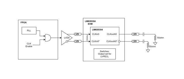
I'm using the LMK00304EVM for buffering a digital clock, before filtering to use as an RF tone.

We need to be able to turn the source on and off, sometimes fairly rapidly.

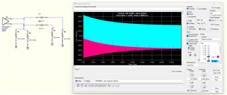
What I'm observing is that the amplitude gets higher when the clock input is turned off/on rapidly.

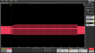
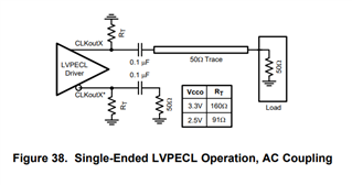
Shown above is an LVPECL output, terminated to two 50 ohm resistors. 

It takes nearly 10mSec for the output to settle back on steady-state.

Technically this doesn't violate anything I'm seeing in the datasheet, but also, this doesn't seem like expected behavior to me.

  • Hi Andrew, 

    I'm not sure I follow the waveform that you sent, to me it doesn't look like toggling the input on/off but instead it looks more like you're temporarily decreasing the input frequency. If this was the case it would make sense to see the output amplitude increase in this section (see Figure 1 of the datasheet for VOD vs. frequency). Would you be able to capture another plot with the input on one channel and the output on another to see them side by side? 

    Regards, 

    Connor 

  • Hi Connor,

    Sorry, I should have explained better.

    Here is a rough diagram of our setup:

    We have a clock at a constant frequency generated by a PLL in an FPGA. That clock signal is then enabled/disabled based on when we need the tone to stop.

    The scope capture I shared is the envelope of one of the LVPECL outputs, zoomed way out.

    I annotated the scope plot, hopefully this makes it more clear?

    The "gaps" you see in the envelope is when we are disabling the clock. At steady state, the amplitude of the clock is roughly constant. When the input clock is re-enabled, the output of the LMK00304 is at a higher amplitude than expected.

  • Hi Andrew, 

    Thanks for the clarification, I think I understand the setup now. One thought I have is that the behavior you're seeing could be from the AC coupling capacitors fully charging/discharging while the output is disabled, which shifts the common mode of the output. I ran an IBIS simulation as an example with 100nF AC-coupling capacitors and it takes somewhere around 20us for the output to settle around a steady state. At the beginning of the simulation, the P output swings between around 0V and 850mV, and the N output swings between 0V and -850mV. This wouldn't fully explain what you're observing where it takes more like 10-20ms to reach steady state (unless you have very large AC-coupling capacitors that have require a longer RC time constant to charge/discharge) but it could result in some strange looking waveforms. 

    Another question, do you have resistors to GND on the LMK00304 outputs before AC-coupling? LVPECL drivers usually need emitter resistors to provide a DC bias for the emitter follower stage of the output driver. If these resistors are missing then your output might not behave as expected. On our datasheet it looks like we recommend using 160 Ohms: 

    Regards, 

    Connor 

  • Hi Connor,

    We haven't modified the board, besides de-popping the 0 ohm resistors on channels that aren't used (per the datasheet). I missed those in my sketch.

    I thought the same thing with the coupling caps... Actually, now that you bring that up, it looks like the input side has AC caps... And no resistors to GND...

    Any idea what the input impedance is? If it's high-Z, could that explain the long TC?

  • Connor,

    Looks like the input AC coupling was the issue!

    The board had the AC caps where circled, but I see there are markups on the schematic in red? It looks like the red markups apply the fix for the issue I was seeing.

    Best,

    Andrew

  • Great, I'm glad that resolved your issue! LMK00304 has a high input impedance (internal 500k pullup and 250k pulldown on CLKin+, 500k pullup and 350k pulldown on CLKin-), so if you don't have an external termination resistor the time constant for the AC coupling capacitors could be very long. 

    I'll go ahead and mark this thread as resolved if you don't have any other questions. 

    Regards, 

    Connor