This thread has been locked.

If you have a related question, please click the "Ask a related question" button in the top right corner. The newly created question will be automatically linked to this question.

LMX2492EVM: VCO Replacement

Part Number: LMX2492EVM
Other Parts Discussed in Thread: LMX2492

Tool/software:

Hello,

We have recently purchased the LMX2492EVM and would like to clarify a few details regarding VCO replacement.

Our goal is to replace the onboard VCO on two separate occasions - one time with a VCO for the 5.8 GHz band and another time with a VCO for the 2.4 GHz band. Since the board has only one VCO slot, we plan to swap between these two VCOs for testing purposes.

We would appreciate guidance on the key parameters we need to verify before purchasing, such as physical size, tuning voltage range, and overall compatibility with the LMX2492EVM.

The two VCOs we are considering are:
CVCO55CC-2328-2536 (2.4 GHz)

CVCO55CXT-5700-5900 (5.8 GHz)

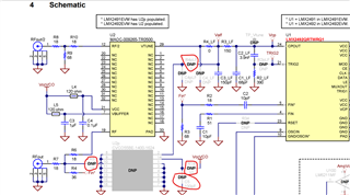
Additionally, we understand that replacing the VCO will require modifying certain resistors and capacitors on the board. Could you provide guidance or reference materials on how to properly calculate the required resistance and capacitance values to ensure optimal VCO operation for each of these two cases?

We appreciate your support and look forward to your advice.


CVCO55CC-2328-2536.pdfCVCO55CXT-5700-5900.pdf

  • Hi Michel,

    CVCO55 series footprint fits the eval board.

    Frequency range and phase noise of the VCO are the key parameters that must suit your application need.

    Other key parameters, such as tuning sensitivity and input capacitance are used for the loop filter design. 

    To design the loop filter, suggest use PLL sim (https://www.ti.com/tool/PLLATINUMSIM-SW). 

    If you are interested in PLL theory and design, visit our video training page.

    https://www.ti.com/video/series/precision-labs/ti-precision-labs-introduction-to-clocks-and-timing.html

  • Thank you for your response!

    After verifying the parameters and ensuring that our selected VCOs are compatible, we noticed that several resistors and capacitors - such as R5, R14, C5, and R4pLF - appear to be essential for proper operation, but they are not included in the simulation you provided.

    Could you clarify whether the values specified in the datasheet apply universally, regardless of the VCO being implemented? Or do they need to be adjusted based on the new VCO parameters? Additionally, are there any other components that require modification or replacement that we may have overlooked?

    Furthermore, we would like to confirm whether the internal VCO can be disabled directly through TI’s GUI, or if a physical disconnection is required on the circuit to ensure proper operation with the external VCO.

    We appreciate your guidance and look forward to your response!

  • Hi Michel,

    R14 and C5 are the supply filtering for the VCO. 

    You need R5 to connect the output of the VCO to the SMA connector and PLL Fin*.

    R4pLF and C4pLF forms the 4th pole of the loop filter. If your loop filter is less than 4th order, you don't need them, but R4pLF should be 0Ω. 

    LMX2492 is a PLL, it does not contain VCO. 

  • I would like to ask a few more questions regarding the LMX2492EVM configuration.

    External VCO Integration:
    Since we plan to connect an external VCO, we would like to know if there are any specific steps required to disconnect the internal VCO to ensure that only the external VCO is used. Additionally, do we need to modify any settings in TI’s TICS Pro software to accommodate this change?

    Open Loop Sweep Configuration:
    We intend to perform the frequency sweep in open-loop mode, where the PLL does not continuously lock onto the frequency, allowing for a faster sweep. How exactly can we configure this mode? Does enabling ramps automatically transition the system into open-loop operation, or are there additional settings we need to modify?

    Power Supply Connection:
    According to the schematic, the 5V supply voltage needs to be connected through the SMA connection. Is this the only way to power the LMX2492EVM, or is there an alternative method? If the SMA connection is required, do we need a specific adapter to connect a standard power supply to the SMA input? do you sell any cables or adapters from this kind?

    RF Output Termination:
    In the provided schematic, we noticed that one RF output is connected to a 50-ohm termination resistor, while the other output is connected to the spectrum analyzer. Is it necessary to connect the 50-ohm termination resistor, or can we leave it disconnected without affecting performance?

    We appreciate your support and look forward to your response.

  • Hi Michel,

    This PLL (and the ramp engine) is design to work in a closed-loop system. If you open the loop, the ramp engine is not able to ramp the VCO. 

    The SMA connector is just an interface, you can use any wire to connect the EVM and a power supply.

    Which termination resistor?

  • Before proceeding with the connection, we want to confirm the necessary steps, as we already have the external VCOs in hand and are ready to integrate them.

    To properly connect the external VCO, we will install it in its designated spot and ensure that R5, R14, C5, and R4PLF are in place so that our VCO is correctly connected to the loop filter.

    However, we need clarification on how the EVM determines whether to use the internal or external VCO. Specifically, do we need to disconnect R6 to prevent the internal VCO from outputting an RF signal? Additionally, should R4LF be removed to prevent the internal VCO from receiving input from the loop filter?

    Your guidance on these points would be greatly appreciated.

  • Hi Michel,

    The onboard VCO has to be powered down, remove L4 and L5. Also remove R6 and R4_LF to disconnect this VCO from U2p and U1.