This thread has been locked.

If you have a related question, please click the "Ask a related question" button in the top right corner. The newly created question will be automatically linked to this question.

CDCE913: CDCE programming issue (?) Output frequency double than what is expected

Part Number: CDCE913
Other Parts Discussed in Thread: CLOCKPRO

Tool/software:

Hello again Kareem

The saga continues:  I have one more problem with the CDCE913.

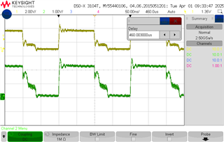
I programmed the part on the programmer board and installed it in my prototype.  It works but outputs twice the programmed frequency.

I did scope both Input and output waveforms and there is no horrible glitches or something that looks very wrong.

Any chance that the programming file from ClockPro has some issue?  Or something else I am missing?

I did not try to reverse engineer the file.  I still am not too sure about the expected Q and R values.

The CDCE913 is supposed to generate a 32.768Mhz output from a 10Mhz one from a GPS reference.  LVCMOS input.

Xout is left open.  

But the actual output from the part is 65.536Mhz

I do include the programming file from clockprofmt5.TXT

Hopefully, you have some idea.  As it is, I am quite confused.

Best regards,

Robert

  • Robert,

    We should be able to take a look at this on the bench and set you know if we see any issue tomorrow. Initial review of the configuration does not reveal anything that seems to be wrong.

    In the meantime, can you provide images of the input and output waveform?

    Thanks,

    Kadeem

  • Hello Kadeem

    It seems that I wasted your time.  Sorry about that.

    There is nothing wrong with the CDCE913 or its programming except maybe that it is somewhat more touchy on its input waveform that I would have expected.

    Unfortunately, the GPS output is 3.3V.  I realized only after the test board layout that the CDCE913 frequency input is 1.8V level.  So I kludged in a 74AUC1G17 as a level shifter.  That is the problem:  not a good level shifter.  The 1G17 messes the waveform enough to confuse the CDCE913.  And I did not notice immediately as I was probing the input at the GPS simulator output (I do use a simulator circuit at this stage) and not after the 1G17.  Nevertheless, I did not think that the 1G17 output was bad enough to create the problem.

    I tried again this morning, replacing the GPS simulator circuit by a signal generator for a nicer waveform and the CDCE913 now works as expected.

    The problem is clearly in my own ballpark.  I have to find a better drive/level shifting circuit.  I will deal with that.

    I do include scope pictures, as requested, in the hope that it helps you with future issues.  Please note that I had reduced the input frequency to 5Mhz, cheating to get the right output with the problem, to be able to test other circuits.

    Left picture is the input. Top trace before 1G17 and lower trace after, CDCE913 input.

    Right picture the CDCE913 output.  There may be a bit of probe ringing on all of these.

    I now understand that the CDCE913 needs a very clean input.  While the drive is far from as clean as I would like, I did not think that bad enough to create a problem.  Anyway, I can fix that.

    Again sorry to have overreacted and wasted a bit of your time.

    Thank you very much for your timely response and it is now up to me to fix the issue.

    Have a great day

    Robert

  • Robert,

    Glad the issue was able to be resolved and thank you for sharing this information!

    Best,

    Cris