This thread has been locked.

If you have a related question, please click the "Ask a related question" button in the top right corner. The newly created question will be automatically linked to this question.

LMK5B12204: Ultra-Low Jitter Network Synchronizer Clock With Two Frequency Domains

Part Number: LMK5B12204

Tool/software:

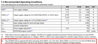
In VDDO_x where these are referred as output pins and it is told to connect to Output Supply (1.8, 2.5, or 3.3 V) for Clock Outputs 0 to 3 what does that mean, for application should i power these nodes to those supplies , are these 1.8,2.5,3.3 is the swing of the supply, If i have to connect these VDDO pins to those voltages should i generate them from different source and whats the current consumption, and what happens to the output if i connect to these different voltages?

  • Hi Yatish,

    I will review your question and get back to you later today or tomorrow.

    Regards,

    Jennifer

  • Hi Yatish,

    There are two supply pin types on the LMK5B12204: VDDx and VDDOx. The VDDx pins power the core supplies of the device, such as the APLL1 or input buffers. The VDDOx pins power the output-related supplies of the device such as the output buffers.

    The device can be in normal operation and meet the datasheet spec when VDDx are applied 3.3V nominally (see min/max spec in the datasheet) and VDDOx pins are applied either 1.8V, 2.5V, or 3.3V. Depending on your application, you may want to use 1.8V for VDDO to get lower power. Some applications only have a 3.3V supply rail available and in that case, VDDOx is applied 3.3V. Mixing is also acceptable: for example, you can have 1.8V applied to VDDO_0 and 3.3V applied to VDDO_2.

    If an LVCMOS output is used, per datasheet footnote (see below picture), a 1.8V supply is recommended for that VDDOx pin.

    Does this answer your question?

    Regards,

    Jennifer