This thread has been locked.

If you have a related question, please click the "Ask a related question" button in the top right corner. The newly created question will be automatically linked to this question.

CDCE62005* INTERFACE

Guru 13485 points
Other Parts Discussed in Thread: CDCE62005, CDCLVP1102, ONET1191P

For CDCE62005:

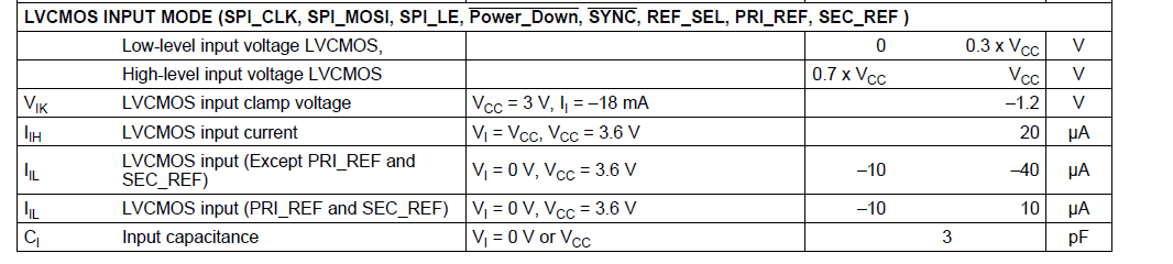
What is the recommended way to interface in LVCMOS Single mode ?


What is the DC level ? what is the AC level ? should the signal be a perfect sine wave or can it be a perfect clock ?


What is the best way in the manner of integrated phase noise ?

Eli

  • Hi Eli,

    the recommended way to use the LVCMOS interface is to use the PRI_REF+ (and connect the PRI_REF- with a 1k Pull-Down resistor to GND) or the SEC_REF+ (and connect the SEC_REF- with a 1k Pull-Down resistor to GND). Either of the two options have the same influence on Phase Noise performance.

    The datasheet specifies the recommended parameters for the LVCMOS clock input, as you can see in the attached screen-shot.

    Best regards,

    Leandro


  • Hi Eli,

    in addition to Leandro's comments, for best phase noise you want the fastest possible input slew rate (so use a clock signal instead of a sine wave if possible).

    Best regards, Falk Alicke

  • Fritz,

    What is the trade of caused by using clock signal instead of pure sine wave or clipped sine ?

    We intend to use a "NOT Gate " to convert sine wave to clock signal at 10MHz,

    We have a target of < 1PSec jitter ( the CDCE feeds ADC IC)

    Do you have any recomendation for such "Not Gate" ?


    Thanks

    Tal Bareket

    Sr RF Eng

    Novelsat

  • Hello Tal,

    The ideal input stage of a clock buffer of clock generator would be a limiting amplifier with unlimited input gain. Practically however, you find that the gain is limited and therefore any noise on the input signal and any noise due to the input buffer input stage will have a higher jitter impact at slower rise times. If you recorded the jitter after an input buffer, you would find a graph that shows a fixed amount of added jitter for very fast rise times, and as you reduce rise time more and more, you suddently start seeing the noise on the buffer output to increase exponentially. It is advisable to keep the input signal slew rate higher than this turning point. That is why you different devices will have a differing minimum input slew rate requirement. It is not that the device could not operate with a slower signal, but you will see increased phase noise on the device output due to the input buffer starting to limit the INBAND NOISE of the PLL.


    The slew rate for a sine wave is directionally proportional the sine wave amplitude and the sine wave frequency. For a 10MHz sine wave with 3.3V amplitude, the slew rate comes out to roughly 0.21V/ns. In comparison, the output slew rate of a typical differential clock signal is between 1V/ns (LVDS) and 5V/ns (PECL). The CDCM62005 LVCMOS output slew rate is 3.6V/ns typically.


    The CDCM62005 requires an input slew rate of faster than 1V/ns to guarantuee the jitter performance specified in the data sheet. With the 10MHz sine wave of 3.3V you will see some performance degradation. If you use an inverter gate to convert the sine wave into a clock signal, you will see one of three things:

    1. If the inverter gate has a slow input stage, the overall jitter performance will be worse than driving the CDCE62005 directly from the sine wave

    2. If the inverter gate has the same input stage behavior as the CDCE62005, the performance with or without inverter will be roughly the same.

    3. Only if the inverter gate has a very fast input stage (very high-gain amplification) will you see an overall improvement.

    Of course you are aiming for #3. Therefore we recommend using a signal buffer that can support very high frequencies, as such buffers typically also provide very responsive input stages. I've attached a measurement on this parameter for the CDCLVCP120x family. This measurement would apply to a CDCLVP1102 as well. As you can see, right around 0.2V/ns you see increased sensitivity to input noise. 

    5684.CDCLVP1204 _ Additive Jitter vs. Input Edge Rate.pdf 


    I suspect the best choice to really speed up edges would be a limiting amp like a ONET1191P. (http://www.ti.com/product/onet1191p)

    Question: for your 1ps jitter requrement, what is the integration bandwidth? Depending on your requirements it might be ok to drive the CDCM62005 directly. Please let us know.


    Much thanks! BR. Falk

  • Hi Fritz

    I would like to thank you for your promt and thorow response.

    the integration BW is ~ 1MHz.

    Currently we are using a clipped sine wave. I will measure the  slew rate to verify its performance compare to 1V/nSec

    It may be that it is OK with this criteria.

    Thanks

    Tal Bareket

  • Hi Tal, you are most welcome!

    By the way, I checked with the engineer supporting the ONET1191P. If this was something necessary, he would do the follwowing connection:


    sinewave (single ended) --> AC cap --> P-input (ONET) --> 100 Ω --> N-input (ONET) --> 50 Ω --> AC cap --> GND

    on the output, he recommended to simply AC couple the differential outputs.


    Best regards, Falk