This thread has been locked.

If you have a related question, please click the "Ask a related question" button in the top right corner. The newly created question will be automatically linked to this question.

AFE7950EVM: Frequency Drifting issue even after pll is locked.

Part Number: AFE7950EVM
Other Parts Discussed in Thread: AFE7950, TRF1208, TRF1208EVM

Tool/software:

Hey sir/ma'am,

With AFE7950EVM and MPF300t (fpga), we established serdes link and can able to transfer data between those. But issue is when we are trying to send the pattern data using latte software, frequency is drifting as mentioned is the below video:

Code used is pinned below:

##############		Read me			##############
#In HSDC Pro DAC tab, Select AFE79xx_2x2TX_14810; Data Rate = 122.88M
#In HSDC Pro ADC tab, Select AFE79xx_2x2RX_14810; Data Rate = 122.88M

sysParams=AFE.systemParams
sysParams.__init__();sysParams.chipVersion=chipVersion

setupParams.skipFpga = 1 # setup FPGA (TSW14J56) using HSDC Pro 
##############		Top Level			##############
sysParams.FRef			= 491.52
sysParams.FadcRx		= 2949.12
sysParams.FadcFb		= 2949.12
sysParams.Fdac			= 2949.12*4
sysParams.externalClockRx=False
sysParams.externalClockTx=False
sysParams.RRFMode		= 0					# RRF 0: 4T4R2F FDD Mode
sysParams.enableDacInterleavedMode=False
													
##############		Digital Chain		##############

		#####	RX	#####
sysParams.ddcFactorRx	=	[24,24,24,24]			#DDC decimation factor for RX A, B, C and D
sysParams.rxNco0		= 	[[9500,9500],			#Band0, Band1 for RXA 
							[9500,9500],        		#Band0, Band1 for RXB 
							[9500,9500],        	#Band0, Band1 for RXC 
							[9500,9500]]        	#Band0, Band1 for RXD 

		#####	FB	#####
sysParams.ddcFactorFb	=	[6,6]					#DDC decimation factor for FB 1 and 2
sysParams.fbNco0		= 	[4000,4000]				#Band0 for FB1 and FB2 
sysParams.fbEnable		=	[False,False]

		#####	TX	#####
sysParams.ducFactorTx	=	[96,96,96,96]			#DUC interpolation factor for TX A, B, C and D
sysParams.txNco0		= 	[[9500,9500],			#Band0, Band1 for TXA 
							[9500,9500],        		#Band0, Band1 for TXB 
							[9500,9500],        	#Band0, Band1 for TXC 
							[9500,9500]]        	#Band0, Band1 for TXD


##############		JESD		##############

		#####	ADC-JESD	#####
sysParams.jesdSystemMode= [3,3]
													#SystemMode 0:	2R1F-FDD						; rx1-rx2-fb -fb
													#SystemMode 1:	1R1F-FDD						; rx -rx -fb -fb
													#SystemMode 2:	2R-FDD							; rx1-rx1-rx2-rx2
													#SystemMode 3:	1R								; rx -rx -rx -rx
													#SystemMode 4:	1F								; fb -fb- fb -fb
													#SystemMode 5:	1R1F-TDD						; rx/fb-rx/fb-rx/fb-rx/fb
													
sysParams.jesdTxProtocol= [0,0]						# 0 - 8b/10b encoding; 2 - 64b/66b encoding 
sysParams.LMFSHdRx		= ["14810","14810","14810","14810"]
													# The 2nd and 4th are valid only for jesdSystemMode values in (0,2).
													# For other modes, select 4 converter modes for 1st and 3rd.
sysParams.LMFSHdFb		= ["22210","22210"]

sysParams.rxJesdTxScr	= [False,False,False,False]
sysParams.fbJesdTxScr	= [True,True]

sysParams.rxJesdTxK		= [8,8,8,8]
sysParams.fbJesdTxK		= [8,8]

sysParams.jesdTxLaneMux	= [7,1,2,3,6,5,4,0]			# Enter which lanes you want in each location. 
													# For example, if you want to exchange the first two lines of each 2T,
													#		this should be [[1,0,2,3],[5,4,6,7]]

		#####	DAC-JESD	#####
sysParams.jesdRxProtocol= [0,0]
sysParams.LMFSHdTx		= ["14810","14810","14810","14810"]
sysParams.jesdRxLaneMux	= [6,4,2,3,7,5,1,0]		#[7,6,2,3,4,5,1,0] #0,1,2,3,4,5,6,7]			# Enter which lanes you want in each location.
													# For example, if you want to exchange the first two lines of each 2R
													#		this should be [[1,0,2,3],[5,4,6,7]]
sysParams.jesdRxRbd		= [3, 3]
sysParams.jesdRxScr		= [False,False,False,False]
sysParams.jesdRxK		= [8, 8, 8, 8]

		#####	JESD Common	#####
	
sysParams.jesdABLvdsSync= True
sysParams.jesdCDLvdsSync= True
sysParams.syncLoopBack	= True	#JESD Sync signal is connected to FPGA

##############		GPIO		##############
sysParams.gpioMapping	= {
						'H8': 'ADC_SYNC0',
						'H7': 'ADC_SYNC1',
						'N8': 'ADC_SYNC2',
						'N7': 'ADC_SYNC3',
						'H9': 'DAC_SYNC0',
						'G9': 'DAC_SYNC1',
						'N9': 'DAC_SYNC2',
						'P9': 'DAC_SYNC3',
						'P14': 'GLOBAL_PDN',
						'K14': 'FBABTDD',
						'R6': 'FBCDTDD',
						'H15': ['TXATDD','TXBTDD'],
						'V5': ['TXCTDD','TXDTDD'],
						'E7': ['RXATDD','RXBTDD'],
						'R15': ['RXCTDD','RXDTDD']}

##############		LMK Params		##############
lmkParams.pllEn			= True
lmkParams.inputClk		= 1474.56 # Valid only when lmkParams.pllEn = False
lmkParams.lmkFrefClk	= True
setupParams.fpgaRefClk	= 245.76 # Should be equal to LaneRate/40 for TSW14J56

##############		Logging		##############
#logDumpInst.setFileName(ASTERIX_DIR+DEVICES_DIR+r"\Afe79xxPg1.txt")
logDumpInst.setFileName(ASTERIX_DIR+DEVICES_DIR+r"\Piersight_4000.txt")
#logDumpInst.logFormat=0x0
logDumpInst.logFormat=0x01
logDumpInst.rewriteFile=1
logDumpInst.rewriteFileFormat4=1
device.optimizeWrites=0
device.rawWriteLogEn=1

device.delay_time = 0
#-------------------------------------------------------------------------------------------------#
#line 119 changes ps
sysParams.useSpiSysref=True
AFE.deviceBringup()

AFE.TOP.overrideTdd(15,3,15)	# bit-wise; 4R,2F,4T
for i in [0,1]:
	for j in [0,1]:
		AFE.JESD.DACJESD[i].dacJesdConstantTestPatternValue(1,j,0,32767,0) # enable, channelNum, bandNum, Ival, Qval


We verified pll is locked,(by reading 0x66 register and it turned out to be 0x33(value)).

This kind of drifting cause major problem for us. plss look into this issue.

Thanks & regards
Akula Vamsi
Piersight Space
Digital design engineer

  • Hi Akula,

    The reason you are seeing is that both the AFE and Spectrum Analyzer are free running. To avoid this issue you can frequency lock the two by providing a 10MHz reference to both the spectrum analyzer and AFE7950, though J14. You could even take the 10MHz reference output from the back of the spectrum analyzer and provide that to the AFE EVM through SMA J14, LMK_CLK_IN. Please test this on your setup and the issue should go away. 

    Regards,

    David Chaparro 

  • hey david,

    i have 3 questions regarding your suggestion on this problem statement.

    1.if i am not wrong , taking reference clock from spectrum analyzer (10mhz) and feeding to j14(REF_CLK_LOW) and j15(LMK_CLK_IN) is the locking process right?

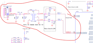
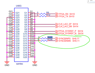
    2.any hardware changes need to be done for below mentioned paths (like DNI need to be included or removal of included components)

    3. any latte code changes need to be done from below mentioned snippet.

    ##############		Read me			##############
    #In HSDC Pro DAC tab, Select AFE79xx_2x2TX_14810; Data Rate = 122.88M
    #In HSDC Pro ADC tab, Select AFE79xx_2x2RX_14810; Data Rate = 122.88M
    
    sysParams=AFE.systemParams
    sysParams.__init__();sysParams.chipVersion=chipVersion
    
    setupParams.skipFpga = 1 # setup FPGA (TSW14J56) using HSDC Pro 
    ##############		Top Level			##############
    sysParams.FRef			= 491.52
    sysParams.FadcRx		= 2949.12
    sysParams.FadcFb		= 2949.12
    sysParams.Fdac			= 2949.12*4
    sysParams.externalClockRx=False
    sysParams.externalClockTx=False
    sysParams.RRFMode		= 0					# RRF 0: 4T4R2F FDD Mode
    sysParams.enableDacInterleavedMode=False
    													
    ##############		Digital Chain		##############
    
    		#####	RX	#####
    sysParams.ddcFactorRx	=	[24,24,24,24]			#DDC decimation factor for RX A, B, C and D
    sysParams.rxNco0		= 	[[9500,9500],			#Band0, Band1 for RXA 
    							[9500,9500],        		#Band0, Band1 for RXB 
    							[9500,9500],        	#Band0, Band1 for RXC 
    							[9500,9500]]        	#Band0, Band1 for RXD 
    
    		#####	FB	#####
    sysParams.ddcFactorFb	=	[6,6]					#DDC decimation factor for FB 1 and 2
    sysParams.fbNco0		= 	[4000,4000]				#Band0 for FB1 and FB2 
    sysParams.fbEnable		=	[False,False]
    
    		#####	TX	#####
    sysParams.ducFactorTx	=	[96,96,96,96]			#DUC interpolation factor for TX A, B, C and D
    sysParams.txNco0		= 	[[9500,9500],			#Band0, Band1 for TXA 
    							[9500,9500],        		#Band0, Band1 for TXB 
    							[9500,9500],        	#Band0, Band1 for TXC 
    							[9500,9500]]        	#Band0, Band1 for TXD
    
    
    ##############		JESD		##############
    
    		#####	ADC-JESD	#####
    sysParams.jesdSystemMode= [3,3]
    													#SystemMode 0:	2R1F-FDD						; rx1-rx2-fb -fb
    													#SystemMode 1:	1R1F-FDD						; rx -rx -fb -fb
    													#SystemMode 2:	2R-FDD							; rx1-rx1-rx2-rx2
    													#SystemMode 3:	1R								; rx -rx -rx -rx
    													#SystemMode 4:	1F								; fb -fb- fb -fb
    													#SystemMode 5:	1R1F-TDD						; rx/fb-rx/fb-rx/fb-rx/fb
    													
    sysParams.jesdTxProtocol= [0,0]						# 0 - 8b/10b encoding; 2 - 64b/66b encoding 
    sysParams.LMFSHdRx		= ["14810","14810","14810","14810"]
    													# The 2nd and 4th are valid only for jesdSystemMode values in (0,2).
    													# For other modes, select 4 converter modes for 1st and 3rd.
    sysParams.LMFSHdFb		= ["22210","22210"]
    
    sysParams.rxJesdTxScr	= [False,False,False,False]
    sysParams.fbJesdTxScr	= [True,True]
    
    sysParams.rxJesdTxK		= [8,8,8,8]
    sysParams.fbJesdTxK		= [8,8]
    
    sysParams.jesdTxLaneMux	= [7,1,2,3,6,5,4,0]			# Enter which lanes you want in each location. 
    													# For example, if you want to exchange the first two lines of each 2T,
    													#		this should be [[1,0,2,3],[5,4,6,7]]
    
    		#####	DAC-JESD	#####
    sysParams.jesdRxProtocol= [0,0]
    sysParams.LMFSHdTx		= ["14810","14810","14810","14810"]
    sysParams.jesdRxLaneMux	= [6,4,2,3,7,5,1,0]		#[7,6,2,3,4,5,1,0] #0,1,2,3,4,5,6,7]			# Enter which lanes you want in each location.
    													# For example, if you want to exchange the first two lines of each 2R
    													#		this should be [[1,0,2,3],[5,4,6,7]]
    sysParams.jesdRxRbd		= [3, 3]
    sysParams.jesdRxScr		= [False,False,False,False]
    sysParams.jesdRxK		= [8, 8, 8, 8]
    
    		#####	JESD Common	#####
    	
    sysParams.jesdABLvdsSync= True
    sysParams.jesdCDLvdsSync= True
    sysParams.syncLoopBack	= True	#JESD Sync signal is connected to FPGA
    
    ##############		GPIO		##############
    sysParams.gpioMapping	= {
    						'H8': 'ADC_SYNC0',
    						'H7': 'ADC_SYNC1',
    						'N8': 'ADC_SYNC2',
    						'N7': 'ADC_SYNC3',
    						'H9': 'DAC_SYNC0',
    						'G9': 'DAC_SYNC1',
    						'N9': 'DAC_SYNC2',
    						'P9': 'DAC_SYNC3',
    						'P14': 'GLOBAL_PDN',
    						'K14': 'FBABTDD',
    						'R6': 'FBCDTDD',
    						'H15': ['TXATDD','TXBTDD'],
    						'V5': ['TXCTDD','TXDTDD'],
    						'E7': ['RXATDD','RXBTDD'],
    						'R15': ['RXCTDD','RXDTDD']}
    
    ##############		LMK Params		##############
    lmkParams.pllEn			= True
    lmkParams.inputClk		= 1474.56 # Valid only when lmkParams.pllEn = False
    lmkParams.lmkFrefClk	= True
    setupParams.fpgaRefClk	= 245.76 # Should be equal to LaneRate/40 for TSW14J56
    
    ##############		Logging		##############
    #logDumpInst.setFileName(ASTERIX_DIR+DEVICES_DIR+r"\Afe79xxPg1.txt")
    logDumpInst.setFileName(ASTERIX_DIR+DEVICES_DIR+r"\Piersight_4000.txt")
    #logDumpInst.logFormat=0x0
    logDumpInst.logFormat=0x01
    logDumpInst.rewriteFile=1
    logDumpInst.rewriteFileFormat4=1
    device.optimizeWrites=0
    device.rawWriteLogEn=1
    
    device.delay_time = 0
    #-------------------------------------------------------------------------------------------------#
    #line 119 changes ps
    sysParams.useSpiSysref=True
    AFE.deviceBringup()
    
    AFE.TOP.overrideTdd(15,3,15)	# bit-wise; 4R,2F,4T
    for i in [0,1]:
    	for j in [0,1]:
    		AFE.JESD.DACJESD[i].dacJesdConstantTestPatternValue(1,j,0,32767,0) # enable, channelNum, bandNum, Ival, Qval


    thanks,
    Akula Vamsi
    Digital Design Engineer
    Piersight Space

  • Hi Akula,

    The 10MHz reference only needs to be provided to the SMA J14 (LMK_CLK_IN) for the reference locking. The AFE configuration does not require any changes to support this as the LMK configuration already supports this by default when using the LMK PLL. 

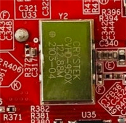
    The only hardware modification required is to remove one resistor, R295, which is on the bottom side of the board next to the 122.88MHz crystal. 

    Once the 10MHz is given to J14 you should see the 'LMK LOCKED' LED, D4, turn on. 

    Regards,

    David Chaparro 

  • hey david,

    Small confusion i am facing actually.
    Document that we are referring to is "6643679A_SCH", in that J15 is LMK_CLK_IN. Which created doubt for R295 resistor, can you confirm once that are you referring to the same resistor that mentioned below.


    for clarification david, we are using (AFE7950_TRF1208) EVM.


    Thanks
    Akula Vamsi
    Digital Design Engineer
    Piersight Space

  • Hi Akula,

    As you mentioned there is a difference between the boards we are referring to. The one I was referencing is the 'AFE7950EVM' which is different from the 'AFE7950_TRF1208EVM'. If you are using the AFE7950_TRF1208EVM then the 10MHz should be given to LMK_CLK_IN, J15. The resistor that needs to be removed, if installed, is R372 (Shown in the picture below). 

    Regards,

    David Chaparro 

  • Hey David,

    Hope you are doing fine.

    Thanks for the input, Drifting Halted after providing with 10mhz ref clock.

    below are the media for reference.


    But need to clarify few things, Because we will be eventually building our custom board from this design, in which frequency drifting will not accept at no cost.


    1-> Do always 10mhz should be provided to LMK_CLK_IN pin to avoid frequency drifting or is it for only spectrum analyzer coherency. To clear this doubt i checked the frequency drifting by taking the input from RF generator and frequency is rigid. only for afe output the frequency is drifting.
    2-> if above is the case do we need to provide a 10mhz ref clock for lmk_clk_in always and poll status_pld_2 , to avoid frequency drifting.

    please put some light on this topic david, We have been badly stuck here from a long time.

    Thanks & Regards
    Akula Vamsi.
    Digital Design Engineer.
    Piersight Space.


  • Hi David,

    Any update on this?


  • Hey David,

    I hope and wish you are doing well.

    Any update on this?

    Kindly please look into this.

    Thanks ,
    Akula Vamsi