Tool/software:
Hi team,
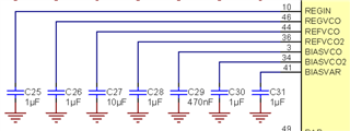
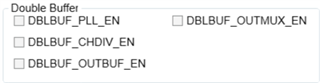
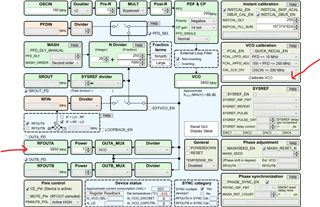
My customer is evaluating LMX2820 and the loop filter parameters are based on the LMX2820EVM default values (C1=470pF, C2=68nF, C3=2.2nF, R2=68.1Ω, R3=18.2Ω)..
the simulated result shows a Lock Time of approximately 88 µs, including the impact of VCO calibration.
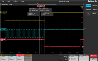
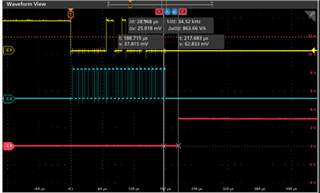
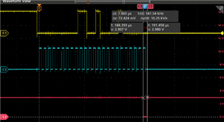
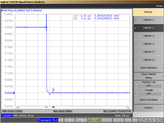
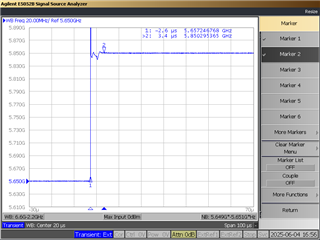
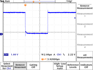
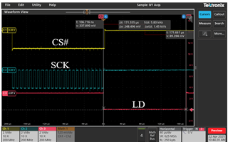
However, in customer HW measurement, the time from SPI transmission completion (CS# goes high) to LD (Lock Detect) pin transition from LOW to HIGH, and it is approximately 171 µs.
customer would like to confirm,
- Is measuring the Lock Time based on LD falling and then rising edge a recommended and reasonable method?
- If we would like to achieve a faster Lock Time (e.g., close to the 88 µs simulation result), would it require specific hardware settings (such as enabling Fast Mode or Instant Calibration)?
- Could you kindly advise the appropriate hardware configuration to achieve closer alignment with the simulated results?
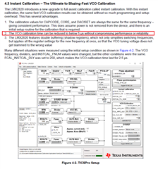
Also in below application note, it states a method to reduce calibration time to below 5us,
https://www.ti.com/lit/an/snaa342/snaa342.pdf
Can we shoe customer how to evaluate the locking time? and below are additional questions from customers.
- The Lock time includes VCO calibration time and analog lock time, am I right ? So the method is only to reduce VCO calibration time, analog lock time depends on hardware loop filter.
- Faster lock setting? GUI set? (as below 4.3 state)
- Can we just check LD pin for total Lock time for LMX2820 to lock? How GUI start to initiate both VCO calibration and frequency change for check total lock time?
Thanks & Regards
Eddie