This thread has been locked.

If you have a related question, please click the "Ask a related question" button in the top right corner. The newly created question will be automatically linked to this question.

LMK04208: Is this configuration possible?

Part Number: LMK04208
Other Parts Discussed in Thread: LMX2594

Tool/software:

Hi, we are working with a design that utilizes the LMK04208 to create a 100MHz signal. We have a 10MHz input and a VCXO at 122.88MHz.

Im using TICS pro to program the LMK with this configuration:
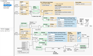
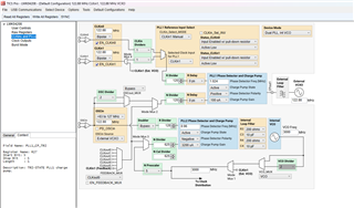
The registers of this configuration are as follows:

R0 (INIT) 0x00160040
R0 0x00140280
R1 0x00143201
R2 0x00143202
R3 0x00140323
R4 0x00143204
R5 0x00143205
R6 0x01100006
R7 0x01600007
R8 0x01010008
R9 0x55555549
R10 0x9102410A
R11 0x0401900B
R12 0x1BCC006C
R13 0x1B02802D
R14 0x0230000E
R15 0x8000800F
R16 0xC1550410
R24 0x00000018
R25 0x02C0FA19
R26 0xAFA8001A
R27 0x10001F5B
R28 0x6001801C
R29 0x01830D5D
R30 0x02030D5E
R31 0x000C001F

We are working with a manufacturers board that can work at other frequencies but i cant seem to lock this frequency.

The board does come with a demo setup that takes 12.8MHz and outputs 122.88MHz. I dont know if its a phase problem on my design or if its even possible to work with these frequencies. Any idea whats happening?

  • Hi Alvaro, 
    Yes, the issue here is the internal VCO frequency. 
    TICSpro isn't throwing an error when it should be. 

    2G VCO is not possible. 
    You can try 3G. 


    Just note a generating 100MHz outputs from 122.88MHz VCXO isn't good in terms of PN performance given the large R & N dividers required to generate 3GHz. 
    Jitter cleaners have integer PLLs, and thus fractional divider values are not possible. 
    Normally PLL2 PFD should be as high as possible which in turn reduces the N divider for most optimal PN performance. 

    I would highly suggest a VCXO of 100MHz, 50 or even 200MHz to generate a VCO frequency that as an integer multiple of 100MHz. 


    Best regards, 

    Vicente 

  • Hi Vicente,

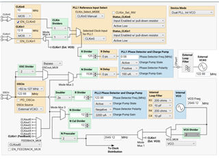
    Thanks for your answer, after testing it on the board it locks the frequency and we can capture with the ADC at our desired frequency. But we are worried about your comments on PN performance and stability of the clock signal. As we have a LMX2594 after the LMK, we have some degree of freedom to find the desired sample frequency for our ADCs (1900MHz). We have changed some numbers to try to get better performance out of the VCOs. Do you think these values are adequate? Would you still change the VCXO to 100MHz instead?

    Best regards,

    Álvaro

  • Hi Alvaro,

    Your value for PFD2 looks better. However, if you want to generate a 3G VCO signal, I would consider using a 100 MHz VCXO. This will allow you to generate your required 100 MHz outputs without sacrificing the phase performance.

    Additionally, I am a bit concerned looking at the new divider values for PLL1. Typically, the best practices include setting your R and N divider values such that N/R simplifies to a whole number (i.e. N must be a multiple of R) - otherwise, you will create multiple phases, and the phase relationship will not be as expected.

    Thanks,

    Michael