This thread has been locked.

If you have a related question, please click the "Ask a related question" button in the top right corner. The newly created question will be automatically linked to this question.

CDCE6214: Termination details

Part Number: CDCE6214
Other Parts Discussed in Thread: CDCI6214,

Tool/software:

Hi team,

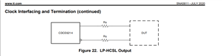
We thought to use CDCE6214RGET part in our design for PCIE gen 3 or Gen 4 application,CDCE6214 will support LP-HCSL output clock technique.

In CDCE6214RGET data sheet not mentioned the RS termination resistor value.

We have one more device for PCIE gen 3 support CDCI6214 part but this is not recommend for the new design.

But in that data sheet termination resistance values are mentioned for PCIE Test Load setup.

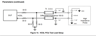
Can you provide the Termination details for PCIE Test Load setup for CDCE6214RGET (LP-HCSL), and CDCE6214RGET  part will have two EEPROM  page (0,1), we are going to use EEPROM PAGE 0 in our design.

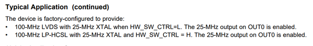
Which is factory program value will reflect on output. We want to know in EEPROM PAGE 0 default factory program frequency value?

  • Thrinesh,

    The CDCE6214 Rs values are left ambiguous to indicate that a resistor should be populated in the event of an impedance mismatch. In some cases, this may help to reduce reflections and ringing due to the mismatch. This is more common with HCSL outputs (CDCI6214), less so with LP-HCSL (CDCE6214).

    The EEPROM Page 0 behavior is described here, for when HW_SW_CTRL is pulled low at startup:

    Thanks,

    Kadeem

  • Hi Kadeem,

    Thanks for your response.

    Our requirement is All output will be 100MHZ LP-HCSL only.

    As per below image says if HW_SW_CTRL pin is HIGH by default factory programed will be 100 MHz LP-HCL, with XTAL 25 MHz input. Our requirement match with this implementation.

    At same time HW-SW-CTRL is high means it will select EEPORM Page 1 and I2C mode slave address is 68h,

    In HW-SW_CTRL is LOW it will disabled  I2C mode. 

    If HW_SW_CTRL pin is HIGH, EEPROM will select Page 1 and factory programmed by default 100Mhz LP-HCSL, and it support  I2C mode also but we are going to operate in Factory programmed  frequency only. No need to programing through I2C. Now we want to know If we not connected I2C instance in CDCE6214 IC it won't make any problem right?

  • Thrinesh,

    No issue if I2C is not connected. These pins can be pulled up to VDD through 1k pull-up resistors if unused.

    Thanks,

    Kadeem

  • Hi Kadeem,

    1. As per CDCE6214-Q1 crystal based oscillator design datasheet mentioned Cint_L1 and Cint_L2  can be programmable through IP_XO_CLOAD register.

    2. But in CDCE6214 datasheet doesn't mentioned about any thing about Cint programmable through IP_XO_CLOAD register. We want to know CDCE614 Will support Programmable for internal load capacitance (Cint)? If yes then how much we can able to tunable load capacitance internally.

    3. CDCE6214 have Constrain for  Crystal load capacitance (CL) - 5pf(min) to 12.8pf(Max) We are going to set CL as 12pf, As per below formula,

    4. We calculated CL1/2 is 6pf and Cstray estimated as 3pf (PCB parasitic capacitance) to achieve 12pf still 3pf margin is there, Where this 3pf can be able to set through IP_XO_CLOAD register?

    5. As per crystal datasheet ESR mentioned as 40 Ohms and we selected RS is 0 Ohms So, Provided ESR+ RS = 40 Ohms. As per below table bias current for 443 uA is 247 is a negative resistance value. As per below image says ESR+RS should be 3-5 times smaller than Negative resistance. But in our scenario it is about 8 times smaller (-R= ESR+RS). Where as -R is 443, ESR is 40 Ohms, RS is 0 Ohms. Will this affect any performance if it is 8 times smaller than negative resistance if Yes then we need to tune the series resister RS? our operating frequency is 25MHZ.

    6. One more thing RS resistor is required or not? 

  • Thrinesh,

    1. This is correct.
    2. The datasheet uses the register address and bit position instead of the field names. See below:
    3. No issue.
    4. The 3pf can be set through the register R24[12:8]. In TICS Pro this is here on the Input page:
    5. I expect that this may not be an issue, but the bias current, on-chip capacitors, and external capacitors can all be adjusted to ensure proper XTAL operation. This can be checked by leveraging the OUT0 output, which is a buffered copy of the reference to the PLL.
    6. RS resistor is not required, and can be 0-Ohm.

    Thanks,
    Kadeem