This thread has been locked.

If you have a related question, please click the "Ask a related question" button in the top right corner. The newly created question will be automatically linked to this question.

LMK05318B: When implementing PTP clock with Intel i210 SDP pin, LOPL-DPLL cannot be cleared. Is the clock frequency valid at this time?

Genius 11230 points
Part Number: LMK05318B

Tool/software:

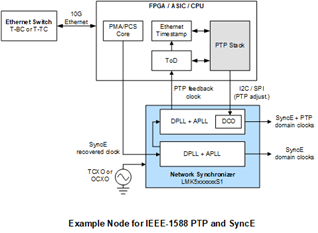
I am currently trying to synchronize the PTP clock output from an Aes67 audio device using Intel i210. The reference clock output from i210 is then filtered/multiplied by LMK05318B to output an I2S clock to downstream devices.

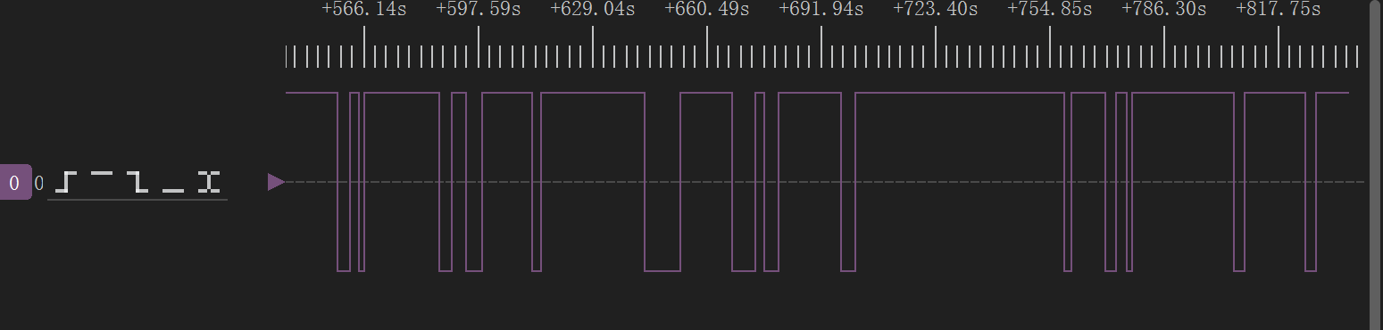
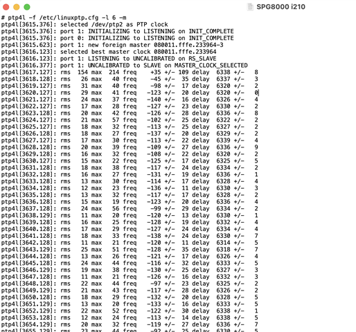
The i210 is controlled by an x86 Linux PC and synchronizes the external clock through Linux's PTP4L. The testPTP program controls the i210's SDP pin to output a 2KHz square wave signal as the reference clock for LMK05318B. The XO crystal oscillator of LMK05318B is a 12.288M TCXO

The PCB used for testing was drawn by myself, and the register configuration currently used for testing is as follows:

  • Hi Links,

    I believe your message got cut off as I do not see the .tcs or hex register file.

    Can you also please restate your question?

    Regards,

    Jennifer

  • Hi Jennifer,

    Yeah, you are correct, sorry for that , please refer to the following files 

    R0	0x000010
    R1	0x00010B
    R2	0x000235
    R3	0x000342
    R4	0x000412
    R5	0x00051D
    R6	0x000619
    R7	0x00072F
    R8	0x000802
    R10	0x000ACA
    R11	0x000B00
    R12	0x000C1B
    R13	0x000D00
    R14	0x000E80
    R15	0x000F00
    R16	0x001040
    R17	0x00111D
    R18	0x0012FF
    R19	0x001300
    R20	0x001480
    R21	0x001501
    R22	0x001600
    R23	0x001755
    R24	0x001855
    R25	0x001900
    R26	0x001A00
    R27	0x001B00
    R28	0x001C01
    R29	0x001D13
    R30	0x001E40
    R32	0x002044
    R35	0x002300
    R36	0x002403
    R37	0x002500
    R38	0x002600
    R39	0x002702
    R40	0x00280F
    R41	0x002900
    R42	0x002A11
    R43	0x002BC2
    R44	0x002C00
    R45	0x002D04
    R46	0x002E88
    R47	0x002F07
    R48	0x00300A
    R49	0x00314A
    R50	0x003202
    R51	0x003300
    R52	0x003400
    R53	0x00350F
    R54	0x003680
    R55	0x003700
    R56	0x003824
    R57	0x003900
    R58	0x003A0F
    R59	0x003B00
    R60	0x003C0F
    R61	0x003D00
    R62	0x003E0F
    R63	0x003FBC
    R64	0x004000
    R65	0x004101
    R66	0x004212
    R67	0x004358
    R68	0x004408
    R69	0x004500
    R70	0x004600
    R71	0x004700
    R72	0x004820
    R73	0x004900
    R74	0x004A00
    R75	0x004B00
    R76	0x004C00
    R77	0x004D0F
    R78	0x004E00
    R79	0x004F01
    R80	0x005000
    R81	0x00510A
    R82	0x005200
    R83	0x005307
    R84	0x005433
    R85	0x005534
    R86	0x005600
    R87	0x00571E
    R88	0x005884
    R89	0x005983
    R90	0x005A00
    R91	0x005B14
    R92	0x005C00
    R93	0x005D07
    R94	0x005E33
    R95	0x005F34
    R96	0x006000
    R97	0x00611E
    R98	0x006284
    R99	0x006383
    R100	0x006428
    R101	0x006501
    R102	0x006644
    R103	0x00670F
    R104	0x00681F
    R105	0x00690D
    R106	0x006A00
    R107	0x006B64
    R108	0x006C00
    R109	0x006D65
    R110	0x006EB9
    R111	0x006FAA
    R112	0x0070AA
    R113	0x0071AA
    R114	0x0072AB
    R115	0x007303
    R116	0x007401
    R117	0x007500
    R118	0x007600
    R119	0x007700
    R120	0x007800
    R121	0x007900
    R122	0x007A00
    R123	0x007BB9
    R124	0x007C76
    R125	0x007D96
    R126	0x007EB5
    R127	0x007FFA
    R128	0x008000
    R129	0x008101
    R130	0x008200
    R131	0x008301
    R132	0x008401
    R133	0x008577
    R134	0x008600
    R135	0x00872A
    R136	0x008800
    R137	0x008947
    R138	0x008A7C
    R139	0x008B03
    R140	0x008C02
    R141	0x008D00
    R142	0x008E01
    R143	0x008F01
    R144	0x009077
    R145	0x009101
    R146	0x0092C6
    R147	0x00930B
    R149	0x00950D
    R150	0x009600
    R151	0x009701
    R152	0x00980D
    R153	0x009929
    R154	0x009A24
    R155	0x009B7B
    R156	0x009C04
    R157	0x009D00
    R158	0x009E7B
    R159	0x009F00
    R160	0x00A000
    R161	0x00A12F
    R162	0x00A27B
    R164	0x00A400
    R165	0x00A500
    R167	0x00A701
    R178	0x00B200
    R180	0x00B400
    R181	0x00B500
    R182	0x00B600
    R183	0x00B700
    R184	0x00B800
    R185	0x00B904
    R186	0x00BA08
    R187	0x00BB00
    R188	0x00BC00
    R189	0x00BD00
    R190	0x00BE2C
    R191	0x00BF00
    R192	0x00C070
    R193	0x00C12B
    R194	0x00C200
    R195	0x00C304
    R196	0x00C4C4
    R197	0x00C5CB
    R198	0x00C600
    R199	0x00C700
    R200	0x00C81D
    R201	0x00C900
    R202	0x00CA04
    R203	0x00CBC4
    R204	0x00CC9D
    R205	0x00CD00
    R206	0x00CE00
    R207	0x00CF15
    R208	0x00D000
    R209	0x00D114
    R210	0x00D200
    R211	0x00D316
    R212	0x00D400
    R213	0x00D514
    R214	0x00D600
    R215	0x00D716
    R216	0x00D800
    R217	0x00D900
    R218	0x00DA00
    R219	0x00DB19
    R220	0x00DC6E
    R221	0x00DD00
    R222	0x00DE03
    R223	0x00DF0D
    R224	0x00E047
    R225	0x00E100
    R226	0x00E200
    R227	0x00E319
    R228	0x00E46E
    R229	0x00E500
    R230	0x00E603
    R231	0x00E70D
    R232	0x00E847
    R233	0x00E90F
    R234	0x00EA10
    R235	0x00EB00
    R236	0x00EC01
    R237	0x00EDE0
    R238	0x00EE00
    R239	0x00EF02
    R240	0x00F0DC
    R241	0x00F16C
    R242	0x00F200
    R243	0x00F300
    R244	0x00F400
    R249	0x00F921
    R250	0x00FA00
    R251	0x00FB03
    R252	0x00FC2D
    R253	0x00FD00
    R254	0x00FE00
    R255	0x00FF00
    R256	0x010000
    R257	0x010101
    R258	0x010200
    R259	0x010300
    R260	0x010402
    R261	0x010580
    R262	0x010600
    R263	0x010700
    R264	0x010826
    R265	0x010925
    R266	0x010AA0
    R267	0x010BA0
    R268	0x010C04
    R269	0x010D00
    R270	0x010E03
    R271	0x010F6E
    R272	0x01101F
    R273	0x01111F
    R274	0x01121F
    R275	0x011313
    R276	0x011413
    R277	0x011513
    R278	0x011609
    R279	0x011709
    R280	0x011809
    R281	0x011907
    R282	0x011A07
    R283	0x011B07
    R284	0x011C1E
    R285	0x011D1E
    R286	0x011E00
    R287	0x011F00
    R288	0x012000
    R289	0x012100
    R290	0x012203
    R291	0x0123C6
    R292	0x012401
    R293	0x012501
    R294	0x012600
    R295	0x012724
    R296	0x012807
    R297	0x012907
    R298	0x012A07
    R299	0x012B01
    R300	0x012C00
    R301	0x012D17
    R302	0x012E1C
    R303	0x012F01
    R304	0x013001
    R305	0x013100
    R306	0x013203
    R307	0x01332D
    R308	0x0134CD
    R309	0x013555
    R310	0x013655
    R311	0x013755
    R312	0x013855
    R313	0x013955
    R314	0x013AFF
    R315	0x013BFF
    R316	0x013CFF
    R317	0x013DFF
    R318	0x013EFF
    R319	0x013F03
    R320	0x014000
    R321	0x01410A
    R322	0x014200
    R323	0x014300
    R324	0x014400
    R325	0x0145C0
    R326	0x014600
    R327	0x014798
    R328	0x014896
    R329	0x014980
    R330	0x014A00
    R331	0x014B64
    R332	0x014C00
    R333	0x014D00
    R334	0x014EF4
    R335	0x014F24
    R336	0x015000
    R337	0x015198
    R338	0x015296
    R339	0x015380
    R340	0x015400
    R341	0x015500
    R342	0x015600
    R343	0x015700
    R344	0x015800
    R345	0x015900
    R346	0x015A02
    R347	0x015B00
    R348	0x015C00
    R349	0x015D00
    R350	0x015E00
    R351	0x015F00
    R352	0x016000
    R357	0x016528
    R367	0x016F28
    R411	0x019B04

    Add some additional information:

    When ptp4l is not yet running, it can be observed that LOPL-DPLL is in a cleared state for a considerable amount of time. The following figure shows the status pin signal collected by me using a logic analyzer when set to LOPL output in this state (duration of about 5 minutes):

    Once ptp4l is started to synchronize the network card clock to the external clock, LOPL-DPLL will remain in a marked state unless the lock and unlock thresholds in DPLL phase lock detection are increased

    A new question:
    The manual clearly states that the parameters in DPLL phase lock detect should not be modified. These parameters are only used for debugging. So, what impact will modifying these parameters have on the output clock?

    Regards,

    Links

  • Hi Links,

    Is it possible to also share the .tcs file used to export the hex file?

    Also, please make sure you are using the latest TICS Pro (v1.7.9.0) to generate the file.

    The LOPL parameters are for the status flag. If you widen the threshold, then you are allowing the LOPL flag to clear with more REF input to VCO output phase error. If you tighten the thresholds, then the LOPL flag will take longer to clear as more time is required for the DPLL to update and reduce the REF to VCO phase error.

    I will take a look at your file and will reply early next week with findings.

    Regards,

    Jennifer

  • Links,

    I reviewed your file and can get the DPLL to phase and frequency lock, LOPL = 0 and LOFL = 0.

    When you say that the LOPL = 1 when ptp4l is used, does that mean you are using the DPLL DCO functionality?

    Please elaborate more on the ptp4l use case with LMK05318B:

    • What is the rate of PTP/DCO updates?
    • How much (in ppm) is the frequency adjustment? What is the highest adjustment value the PTP4l makes?
    • What is the your DPLL LBW setting? If possible, please share the .tcs file so I can easily identify this information.

    Regards,

    Jennifer

  • Hi Link and Jennifer,

    I understand that the LMK is updated continuously by i210's frequency output.

    I would be more doubtful about the ptp locking.
    Assuming the i210 circuit is based on the reference design like Intel I210-T1 board.
    And using the upstream igb driver, one can use the perpps userspace tool to use the arbitrary freq feature on SDP pin header.
    #perpps -d /dev/ptp0 -P 1,500000

    But how well does the i210 pll follow the ptp master?
    Direct connected i210 to a GM or BC, the ptp4l jitter around 10-100ns is achievable.


    Complete different approach is a customized i210 board with LMK providing the 25MHz clock directly to the i210.
    Preferably even better with modified igb driver with new DCO functionality.
    "igb_ptp.c function igb_ptp_adjfine_82580()"


    Link, does the LMK phaselock in your setup without ptp4l running?
    To eliminate the jitter introduced by ptp following.

    Regards,
    Octo

  • Hi Link,

    To add to Octo's comment, it would be helpful if you can provide a block diagram of the setup, something like this is what I've seen for PTP:

    Regards,

    Jennifer

  • Hi Links,

    Sorry, i missed the mentioned observation that "When ptp4l is not yet running, it can be observed that LOPL-DPLL is in a cleared state for a considerable amount of time."
    But, without the ptp-following introduced jitter the phaselock must be rock solid in the first place to begin with.

    Jitter tolerance in LMK's configuration vs jitter emission from i210 (in following state).
    Keep in mind that the i210's frequency output on SDP pin has phase steps and is not really VCO controlled.


    Video: Real world example of i210 outputing 10MHz on SDP pin1 in ptp following state.
    (I am on a similar project with i210 + LMK05318B jitter cleaner.)

  • It is possible to lock without running PTP4L, but there may be occasional loss of lock (LOPL_SPLL cleared after being briefly marked).

    One of my devices has a noticeable jitter in the PTP clock output, and you can see that the RMS value changes frequently.

    I will try to update the startup configuration items of ptp4l and check the locking situation.

  • The intrinsic jitter in rms value fluctuation is normally around 10-100ns with PTPv2. Maybe slightly lower.
    With 1000BASE-T link capability, the i210 has a core clock of 125MHz (125Mbaud 5-level coded PAM signaling)
    and thus 8ns timestamping and trigger steps. Adjustment (i210 TIMINCA register) is done in resolution of 2-32 nS but that is by calculation/interpolation, aka pulse skipping.

    I wish to share my test with you to have practical numbers.
    Running a test with ptp disciplined i210 PPS out on SDP pin as 1Hz reference for LMK05318B.
    These are numbers from todays testrun in broadcast production environment.
    Telestream SPG8000 GM (GPS locked) -> Arista switch BC-> Netgear AV switch BC -> i210 PPS -> LMK05318B

    #ptp4l -f /etc/linuxptp.cfg -l 6 -m
    ptp4l[560.164]: selected /dev/ptp0 as PTP clock
    ptp4l[560.166]: port 1: INITIALIZING to LISTENING on INIT_COMPLETE
    ptp4l[560.166]: port 0: INITIALIZING to LISTENING on INIT_COMPLETE
    ptp4l[560.276]: port 1: new foreign master 28993a.ffff.7697d7-310
    ptp4l[560.776]: selected best master clock 080011.fffe.233914
    ptp4l[560.777]: updating UTC offset to 37
    ptp4l[560.777]: port 1: LISTENING to UNCALIBRATED on RS_SLAVE
    ptp4l[561.161]: port 1: UNCALIBRATED to SLAVE on MASTER_CLOCK_SELECTED
    ptp4l[561.913]: rms  159 max  196 freq   +128 +/- 102 delay  1961 +/-  10
    ptp4l[562.912]: rms   53 max   82 freq   +114 +/-  39 delay  1972 +/-   5
    ptp4l[563.912]: rms   46 max   82 freq    +59 +/-  63 delay  1967 +/-   7
    ptp4l[564.921]: rms   44 max   85 freq    +32 +/-  58 delay  1975 +/-   4
    ptp4l[565.922]: rms   47 max   87 freq    +70 +/-  62 delay  1971 +/-   3
    ptp4l[566.923]: rms   46 max  106 freq    +23 +/-  58 delay  1979 +/-   2
    ptp4l[567.924]: rms   43 max   71 freq    +56 +/-  57 delay  1965 +/-   4
    ptp4l[568.927]: rms   48 max   96 freq   +119 +/-  37 delay  1958 +/-   3
    ptp4l[569.926]: rms   44 max   65 freq    +17 +/-  38 delay  1967 +/-   5
    ptp4l[570.931]: rms   35 max   65 freq    +48 +/-  48 delay  1970 +/-   2
    ptp4l[571.931]: rms   52 max  121 freq    +54 +/-  72 delay  1967 +/-   4
    ptp4l[572.932]: rms   44 max   68 freq    +59 +/-  60 delay  1968 +/-   6
    ptp4l[573.937]: rms   37 max   61 freq    +27 +/-  45 delay  1967 +/-   3
    ptp4l[574.937]: rms   61 max  151 freq    +52 +/-  85 delay  1956 +/-   9
    ptp4l[575.944]: rms   34 max   54 freq    +81 +/-  42 delay  1963 +/-  13
    ptp4l[576.941]: rms   32 max   70 freq    +44 +/-  41 delay  1972 +/-  11
    ptp4l[577.943]: rms   38 max   82 freq    +24 +/-  48 delay  1969 +/-   4
    ptp4l[578.945]: rms   36 max   88 freq    +55 +/-  48 delay  1968 +/-   5

    Jun 12 13:55:46 buildroot kernel: [  522.659066] igb 0000:0a:00.0 eth0: igb: eth0 NIC Link is Up 1000 Mbps Full Duplex
    Jun 12 14:06:27 buildroot kernel: [ 1220.096709] igb_ptp_enable_i210 (980): PPS enabled on eth0 SDP1
    Jun 12 14:06:37 buildroot kernel: [ 1230.509340] igb 0000:0a:00.0: DPLL SECREF valid
    Jun 12 14:06:37 buildroot kernel: [ 1230.511142] igb 0000:0a:00.0: DPLL Holdover event end
    Jun 12 14:06:40 buildroot kernel: [ 1233.582262] igb 0000:0a:00.0: DPLL frequency locked
    Jun 12 14:09:00 buildroot kernel: [ 1373.863621] igb 0000:0a:00.0: DPLL phase locked
    Jun 12 16:23:20 buildroot kernel: [ 9433.444128] igb 0000:0a:00.0: DPLL Tuning word history update
    Jun 12 18:39:52 buildroot kernel: [17625.115360] igb 0000:0a:00.0: DPLL Tuning word history update
    Jun 12 20:56:24 buildroot kernel: [25816.787711] igb 0000:0a:00.0: DPLL Tuning word history update

    No loss of phase lock first three history updates. (each 8192 sec)
    So, locking LMK on ptp should be very well feasable.
    The i210 PPS output has the same PPM frequency offset as 2KHz freqout on the SDP pin when following the PTP GM.

    Links, did you apply a LMK softreset after power-on or configuration?
    @Jennifer, is it possible that APLLx VCO Calibration is done too early, even with TCXO?
    I noticed difference in stability when the softreset was done during OCXO heating up.

    Regards,
    Octo

  • Hi Octo,

    1. Can you clarify what you mean bu "difference in stability"? How are you qualifying stability?
    2. Also, if you issues a SWRST too early, did the stability improve over time or remain the same?
      1. The VCO calibration is performed based on the APLL register settings. During holdover (no reference present), the stability of the outputs is based on the stability of the XO input (XO/TCXO/OCXO). If the XO input is not yet stable, then the VCO may also not be stable. SImilarly, if the XO input is not the expected frequency, then the VCO will also not be the expected frequency. The APLL continuously follows and tracks the XO input so I would expect that, over time, the VCO stability and frequency accuracy improves as the XO input stability and frequency accuracy improves.

    Regards,

    Jennifer

  • 1. "difference in stability"
    If the circuit is powered on, the LMK loads eeprom configuration and calibrates the VCO PLL loop as part of the startup.
    DPLL looses sometimes phase lock with PPS from GPS. (XO=24.576MHz ocxo)
    When i apply softreset after reaching ocxo temp of +55C, the DPLL does not loose lock anymore.

    2. Too early is when the oven temperature not yet reached 55C. Start=room temp, end=about 60C. From room temperature till 55 degrees C takes about 2-3 minutes.


  • SC-cut crystal in the OCXO has a frequency deviation of 20 - 30 ppm during warming up.
    With XO=24,576MHz ±0.1 ppm and GPS reference 1PPS.
    I calculated an allowed error between REF and XO of about 2,56 ppm.
    That explains the slow initial locking in my case. With and without softreset it works fine after warming up.
    Described at datasheet LMK05318B-Q1 "8.1.4 Slow or Delayed XO Start-Up"

    Back to the AES67 audio project of Links.
    With XO=12,288MHz ±1,5 ppm TCXO and PTP REF ±10-100ns jitter.
    Allowed error between XO and REF is 5,12 ppm so GPS disciplined PTP will fit very well.

    Ethernet IEEE 802.3 dictates a maximum frequency tolerance of ±50 ppm.
    Intel specifies a frequency tolerance of the timing device to be better than ±30 ppm.
    That means a off-the-shelf NIC is not per-se capable of disciplining the LMK unless you are lucky enough to be within 5,12 ppm.
    That is for the free-run mode without ptp4l.

    @Links: What tolerance do you expect your PTP GM to have? Is it GPS disciplined?

  • Hi Octo,

    Thank you for clarifying. Right, as described in "Slow or Delayed XO Start-Up", I expect until the OCXO has finished warming up, the DPLL may not attain a stable phase lock.

    Hi Links,

    To follow up on Octo's comment, what is the frequency accuracy of your 12.288 MHz TCXO? The more accurate the TCXO is, the more margin the LMK05318B phase validation detector can have.

    Regards,

    Jennifer

  • I will use LMK software reset after configuration, and if burning EEPROM, it will power off and restart hard.

    In my testing process, when there are non PTP packets (which is a daily usage situation), it can be seen in the output log of PTP4L that there is a sudden increase in RMS value in a short period of time:

    ptp4l[28807.082]: rms 46 max 86 freq +10130 +/- 63
    ptp4l[28808.082]: rms 62 max 95 freq +10139 +/- 86
    ptp4l[28809.081]: rms 44 max 85 freq +10173 +/- 57
    ptp4l[28810.081]: rms 56 max 86 freq +10142 +/- 76
    ptp4l[28811.081]: rms 56 max 98 freq +10162 +/- 77
    ptp4l[28812.081]: rms 39 max 72 freq +10175 +/- 53
    ptp4l[28813.081]: rms 59 max 101 freq +10157 +/- 80
    ptp4l[28814.081]: rms 48 max 112 freq +10134 +/- 63
    ptp4l[28815.081]: rms 34 max 58 freq +10124 +/- 44
    ptp4l[28816.082]: rms 33 max 65 freq +10149 +/- 44
    ptp4l[28817.081]: rms 1444 max 4016 freq +10865 +/- 1929 delay 4336 +/- 0
    ptp4l[28818.081]: rms 482 max 674 freq +9695 +/- 91
    ptp4l[28819.082]: rms 108 max 188 freq +9947 +/- 71
    ptp4l[28820.082]: rms 68 max 112 freq +10089 +/- 88
    ptp4l[28821.082]: rms 85 max 138 freq +10184 +/- 87
    ptp4l[28822.081]: rms 54 max 95 freq +10210 +/- 53
    ptp4l[28823.082]: rms 46 max 83 freq +10168 +/- 64
    ptp4l[28824.082]: rms 52 max 86 freq +10181 +/- 72

    If other types of data communication are turned off and only PTP data is available, RMS will remain relatively stable within 100, but this is not feasible in practical use scenarios.

    I have tried various ptp4l configurations, but currently, there are still situations where LMK briefly marks LOPL, with times ranging from a few hundred milliseconds to over ten seconds.

    Will this brief LOPL marking affect the stability and accuracy of the final output clock?

  • Hi Links,

    1. "If other types of data communication are turned off"
      1. Are you referring to the SPI or I2C bus being active for PTP DCO transactions only?
    2. "Will this brief LOPL marking affect the stability and accuracy of the final output clock?"
      1. During the brief LOPL marking, can you check if LOFL and HOLDVR stay 0?
      2. If LOFL = HOLDVR = 0 and LOPL=1, then the outputs have the frequency stability and accuracy of the REF input.
      3. If LOFL = HOLDVR = 1 and LOPL=1, then the device is in holdover. During short-term holdover , the outputs continue to follow the REF input stability & accuracy based on the accumulated tuning word history data. During long-term holdover, the history data is outdated and the outputs have the frequency stability and accuracy of the XO input.
    3. Also, if you are programming the EEPROM with your desired configuration, then a SWRST after boot-up is not necessary because the APLL calibration automatically occurs after loading from EEPROM at start-up. SWRST is recommended if post-boot programming is performed and the APLL registers are modified.
    4. Going back to the TCXO, can you share the datasheet and specs for the part you are using?

    Regards,

    Jennifer

  • Thank you Jennifer for the DPLL part. I will dive deeper into the PTP part of this case.

    Looking at the ptp4l log i see a few things.
    With this particular i210 nic, the LMK can only have stable genlock with phaselock after seeing the PTP GM because the i210 XO has a static freq offset of +10142 ppb. (10.142 ppm > 5,12 ppm alloweble error)
    The rms and peak jitter numbers doesn't look that strange. The variance can happen because of network congestion, packet reordering, asymetric delays. Or maybe a not so obvious config mistake like mixing different PTP profiles in GM or switch BC. (IEEE 1588 clause 19.3.1.1) But this outlier looks like a systematic bug. I believe that it also occurs without other traffic but less frequent, maybe once in few days. PTP is designed for timing + other traffic.
    pub.smpte.org/.../st2059-2-2021.pdf

    On the other hand the goal is to create a SMPTE ST2059 compliant PTP follower and the LMK05318B can save the day as jitter cleaner + timing flywheel.
    See also the ptp4l filtering effect with a frequency jump of 10.149->10.865->9.695->9.947 ppm while ptp glitched almost 4000ns early/late.
    ptp4l software algorithm has a pi loop with kp_exponent = -0.3, ki_exponent = -0.4.

    It would be great if the follower is (much) more imune to disruption and phasesteps than contributed time error by the switch's TC/BC. My experience is that audio is more sensitive to timing distortion than video.

    BTW: i remember there was a i210 driver bug. Shared interrupt, handled by two routines wich can cause external events
    or timestamps to be missed. Please make sure the latest driver is used.

    To rule out the GM, the network switch and even the suspected "double clear" driver bug you can let ptp4l run-in and then disconnect network. i210 generating freerunning but adjusted 2 KHz wave and LMK should lock freq+phase solid. Always done with power cycles to be sure.
    #phc_ctl eth1 freq should show around 10142 ppb with this NIC

    Regards,
    Octo

  • If other types of data communication are turned off "refers to minimizing the transmission of other types of network data on the network, with the most important being RTP multicast protocol packets used by AES67 protocol.

    Can you check if LOFL and HOLDVR remain at 0 during the brief LOPL marking process? ”Throughout the entire operation, both LOFL and HOLDVR remain at 0

    I remember there was an error in the i210 driver program. Sharing interrupts, handled by two routines that may cause external events "I tried using the updated i226v, and the performance of both was almost the same. The problem I encountered should not be caused by an error in the i210 driver program.

    To rule out GM, network switch, and even suspicious "double clearing" driver errors, you can run ptp4l and then disconnect the network. I210 generates idle but the adjusted 2KHz wave and LMK should be locked in frequency and phase stability. Be sure to complete the power cycle. ”I have tried, in this state LMK can be locked and LOPL remains at 0

    Returning to TCXO, could you share the data sheet and specifications of the parts you are currently using? ”The crystal oscillator provided to LMK does not have a data sheet, and the parameters of 3.3-5v and ± 0.1ppm are printed on the casing

  • Hi Links,

    1: other ethernet traffic
    2: Throughout entire operation, LOFL and HOLDVR remain at 0
    good

    3:The i226 is a good successor of the i210 and i agree with you that it's not the NIC or it's driver.
    It uses a different kernel driver igc instead of igb.
    Both chips are well designed, i210 for 1GBASE-T and i226 for 2.5GBASE-T with better jitter spec's, lower power consumption and PCIe PTM.

    4: To rule out GM, network switch..."in this state LMK can be locked and LOPL remains at 0"
    Interesting. By disconnecting (link-down) or without ptp4l running there are no PHC frequency adjustments anymore. In fact the i210/i226 is then freerunning generator, previously adjusted by following the GM, close to 0 PPM.

    5: TCXO parameters of 3.3-5v and ± 0.1ppm.
    This TCXO should be fine. Maybe you can verify the frequency offset if you have a good reference and counter.


    It looks like the ptp4l servo algorithm suffers from the varying network path delay during delay calculation.
    As part of the PTPv2 protocol, the path delay is contiuousely tracked with DELAY_REQ/DELAY_RESP packets.
    But if switch buffers adjust between DELAY_REQ and DELAY_RESP packets the outliers will happen.
    Maybe switching PTP mode BC versus TC (BoundaryClock/TransparantClock) will solve the outliers in this case.
    It's clear that the LMK and i210 are working fine together. All ptp devices on this ethernet switch will have these outliers but it depends on the precision they are working with if you see/hear distortion.
    The linux ptp community is also discussing and working on filtering outliers [1][2]. But on the other side, the outlier should not happen on an industrial PTP enabled network. Linuxptp stack filtering is welcome, hopefully they introduce this.

    The question: Even with LOPL, is the PTP freq/phase tracking within EAS67 broadcast specification?
    Do you have the ability to measure against AES67 + ST2110-10 standard?
    Or simply when received AES67 audio is converted (to AES/EBU or SPDIF), do you hear the distortion?


    [1] sourceforge.net/.../
    [2] gist.github.com/.../5a4dff7e089bd429c5d208d9276e1683

    Regards,
    Octo Halsema