This thread has been locked.

If you have a related question, please click the "Ask a related question" button in the top right corner. The newly created question will be automatically linked to this question.

LMK5C33216: TICS Pro questions

Part Number: LMK5C33216

Tool/software:

Hi team,

My customer have the following questions related to the TICS pro GUI, please help advise on these.

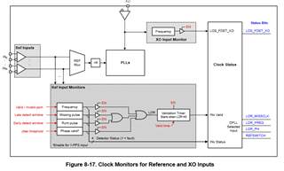
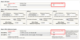
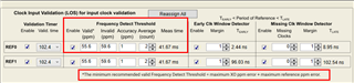
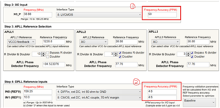
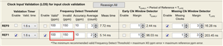
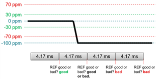
  1. As for part1, what’s the decision mechanism of reference LOS? [More questions such as: why was 100/150ppm chosen as a valid/invalid value for the reference input? And so on…]
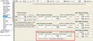
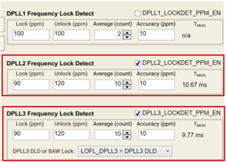
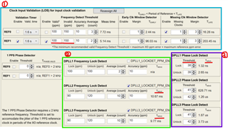
  2. As for part2, what’s the decision mechanism of LOFL? [More questions such as: why was 90/120ppm chosen as a lock/unlock value for the frequency lock detect? And so on…]
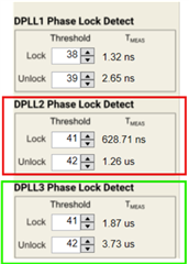
  3. As for part3, what’s the decision mechanism of LOPL? How to select Threshold/Tmeas? What’s the relationship between Threshold/Tmeas and ref jitter?

Thanks and best regards,

Johan

  • Hi Johan,

    Please confirm if you are using the LMK5C33216A or LMK5C33216 (non-A).

    1. LOS and REFx_VALID_STATUS status signals are determined by the enabled REF input detectors. If the enabled detectors all pass (are true) for a given REF input, then that input is considered valid and present by the device. The block diagram below shows the ORing logic involved to set or clear REFx_VALID_STATUS.
      1. 100/150 ppm values that you see in TICS Pro is based on the sum of the XO input frequency accuracy and REF input frequency accuracy, plus some margin. The latest LMK5C33216A profile (v1.7.9.0) helps visualize this.
    2. In the LMK5C33216A profile, the LOFL lock threshold is 1ppm which means that when the frequency error between the REF input and the VCO output reaches 1ppm or less, the LOFL status flag is cleared. The LOFL thresholds can be modified such as to have a larger lock threshold if the user prefers to have the LOFL flag clear sooner (but in turn the error between REF and VCO would be larger at that time LOFL clears).
    3. Similarly, the LOPL thresholds set at what point the LOPL status flag is cleared and checks the phase error between the REF and VCO output. The GUI aims to optimize the LOPL threshold values such that LOPL clears when the phase error between REF and VCO is the smallest possible. The user can also adjust these threshold if they wish to have LOPL clear sooner (but in turn the phase error between REF and VCO at that point in time is larger).

    Let me know if you have further questions.

    Regards,

    Jennifer

  • Hi Jennifer,

    Thank you for your input! They are using the LMK5C33216 (non-A). Some follow up questions:

    1. From our config GUI, the XO ppm error=50ppm, and the OCXO ppm error=4.6ppm, so the minimum recommended valid Freq detect threshold>=54.6ppm (see below figure)

    • But our valid ppm=100, invalid ppm=150ppm(see below figure). The difference between 100ppm and 54.6ppm is bigger. So why do we need to reserve so big margin? How can we evaluate the margin?

    • Another question about ref clock monitoring is that: what’s the relationship between accuracy(10ppm), average(2 count) and Meas time(5.14ms) as shown by above figure? How to select these parameters?

    From datasheet, there describes that: .” A measurement accuracy (ppm) and averaging factor are used in computing the frequency detector register settings. A higher measurement accuracy (smaller ppm) or higher averaging factor will increase the measurement delay to set or clear the flag, which allow more time for the input frequency to settle and can also provide better measurement resolution for an input with high drift or wander. Note that higher averaging reduces the maximum frequency ppm thresholds that can be configured. “ But still can't get a detailed answer to the above questions…

    2.

    • What’s the decision mechanism of LOFL? What I want to say is that: If the ref error exceeds 120ppm for 10 consecutive tests, will LOFL be set to 1?
    • And same question as above, what’s the relationship between LOCK value, Unlock value, accuracy(10ppm), average(10 count) and Meas time(10.67ms in DPLL2 config  / 9.77ms in DPLL3 config) as shown by below figure.   Why are the Tmeas values ​​of DPLL2 and DPLL3 different? What are the related factors? And how to select these parameters of Lock value/Unlock value/Average/Accuacy/Tmeas?
    • If the ref freq error exceeds 120ppm, will DPLL2 and DPLL3 report LOFL at the same time?

    3. 

    • What’s the decision mechanism of LOPL? As shown in below figure, the thresholds between DPLL2 and DPLL3 is same. But Tmeas between DPLL2 and DPLL3 is different. What’s the meaning?
    • The Lock value=41, Unlock Value=42, What does this mean? And What is its unit of measurement? What is the physical meaning between Threshold and Tmeas?
    • Still same question as above,  If the ref phase error exceeds Threshold(don’t know the specific values), will DPLL2 and DPLL3 report LOFL at the same time?

    Thanks and best regards,

    Johan

  • Hi Johan,

    Please allow me to review this on Friday as I will be on business travel the next few days.

    Regards,

    Jennifer

  • Hi Johan,

    1. Ok, if they are using the non-A then I don't advice them to use the "A" version of TICS Pro. This is because there are feature improvements to the "A" silicon version which in turn means there is added register functionality that is not found in the "non-A".
      1. With that said, we customers to migrate to the A version because this is the latest silicon and we are planning to mark the non-A as "not recommended for new designs". Additionally, the "A" TICS Pro profile gets prioritized with the latest software fixes and GUI features.
    2. "But our valid ppm=100, invalid ppm=150ppm(see below figure). The difference between 100ppm and 54.6ppm is bigger. So why do we need to reserve so big margin? How can we evaluate the margin?"
      1. [JB] The same logic applies for both non-A and A version. The valid and invalid thresholds should be based on the XO accuracy + REF accuracy + some margin threshold. Previous TICS Pro profile (non-A) used a wider threshold of 100 ppm by default and does not have the automatic setting based on the XO accuracy and REF accuracy specified in the Start Page. The automatic setting is only found in the "A" TICS Pro profile. The user can reduce the valid/invalid threshold values to match their application. A lower threshold means more stringent and robust input frequency detection.
      2. Regarding the margin to add, we found that 1 ppm margin suffices. That is how much is used in the "A" TICS Pro profile.
    3. "Another question about ref clock monitoring is that: what’s the relationship between accuracy(10ppm), average(2 count) and Meas time(5.14ms) as shown by above figure? How to select these parameters?"
      1. The accuracy sets the resolution of the measurement which impacts the measurement time because it takes more time to measure more precisely.
      2. The average defines the number of measurement samples to capture and average.
    4. "What’s the decision mechanism of LOFL? "
      1. [JB]
      2. The DPLL LOFL bit is a status flag that is used to monitor the phase lock between the input and outputs.
      3. The state of the LOFL bit depends on the frequency error between the DPLL reference (from INx) and the DPLL feedback (from the VCO output). If the LMK device is configured properly, the LOFL is considered frequency locked when the LOFL bit is cleared.
      4. The LOFL bit is cleared when the frequency error is less than the LOFL lock threshold.
      5. The LOFL bit is set when the frequency error is more than the LOFL unlock threshold.
    5. "What I want to say is that: If the ref error exceeds 120ppm for 10 consecutive tests, will LOFL be set to 1?"
      1. [JB] If the averaged result from the 10 samples exceeds 120 ppm then LOFL is set.
    6. "Why are the Tmeas values ​​of DPLL2 and DPLL3 different? What are the related factors? And how to select these parameters of Lock value/Unlock value/Average/Accuacy/Tmeas?"
      1. [JB] The tmeas value is different between DPLL2 and DPLL3 because they are set to different VCO frequencies.
    7. "If the ref freq error exceeds 120ppm, will DPLL2 and DPLL3 report LOFL at the same time?"
      1. [JB] Not exactly the same time because the tmeas is different.
    8. The LOPL flag has a similar logic as the LOFL flag mentioned above.
    9. My recommendation is to use the GUI suggested values for LOPL. The ideal LOPL flag clears when the phase error between the REF input and VCO output is minimal (near 0). However, users may choose to widen the thresholds beyond the recommended GUI setting to make the LOPL clear faster. The DPLL continuously tracks the REF input frequency and phase to correct the APLL numerator; this is regardless of the LOPL and LOFL flag setting. The flags simply are to determine when the user can know that frequency and/or phase lock has been achieved without probing.

    Regards,

    Jennifer