Other Parts Discussed in Thread: LMK5B12204
Tool/software:
Hi,
I need a 250 MHz clock to feed an ADC. My jitter target is < 70 fs.
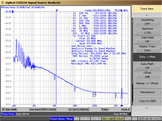
The performance reported in the datasheet, in DPLL mode and APPL1 only, seems to meet my requirement.
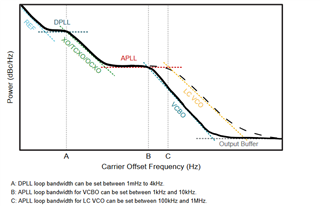
- Is it possible to achieve a jitter < 70 fs using only APLL1 and turning off DPLL?
- What is the disadvantage of not using DPLL?
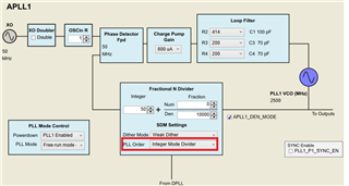
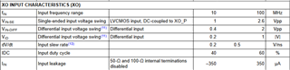
- Can I use a 50 or 100 MHz XO in the case where DPLL is turned off? (The ratio between the input and output frequency of APLL1 would be an integer.)
- What happens if I use DPLL but without the reference (PRIREF or SECREF)? Is this an allowed configuration?
- Can I use a 25 MHz clock from an FPGA as PRIREF for DPLL?
Thanks
Regards
Alberto